This post was imported from my old blog Current Flow.

First of all a bit of a back story: This is my first attempt at a DC-DC converter, I’ve always thought they were magic black-boxes that you just had to accept and building one yourself without a dedicated chip was something extremely difficult, something that could only be done with some high-speed complex analog circuitry or high-speed microcontrollers. I think a lot of people think the same way and I decided to try out my luck and it worked fine, switch-mode converters are not black magic (now only RF is black magic), and I hope I demystify them for you too in this article.
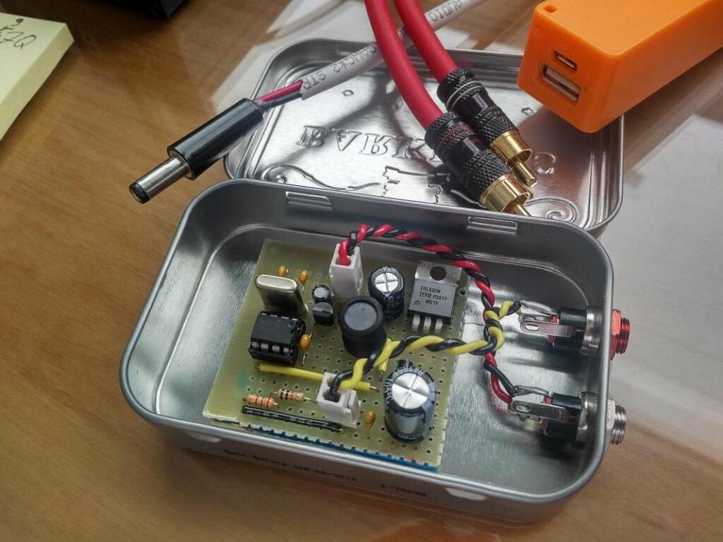
The idea for this project came because I built a nice portable Class-A headphone amplifier (blog post coming in the future) and I wanted a simple power supply for it when I was using it with my computer, so I had to step the 5V from the USB to the 9V required by the amplifier circuit, the amplifier even though it’s Class-A has a low current consumption, so the 2.5W from a normal USB was more than enough. Taking into consideration all this I needed a boost converter with the following specs:
- 5V input at 450mA maximum to work with any USB port
- 9V output able to source up to 110mA (more than enough for my amp)
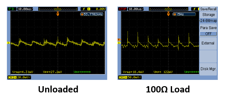
- Acceptable voltage ripple and noise since this will be used with pre-amps and the headphone amp

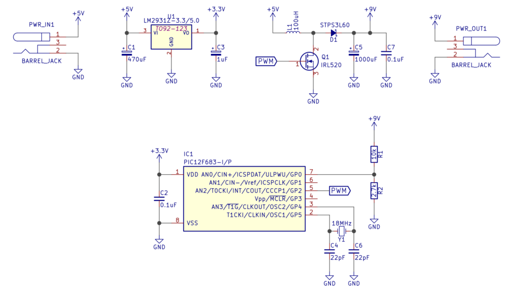
As you can see there’s not a lot happening, and that’s the beauty of this design, since it was made for low power projects it doesn’t require any of the complexities, it was designed to be minimalistic and easy to build for someone that is new to switch-mode converters. The entire feedback control loop is contained inside the PIC12F683 microcontroller, it is a pretty tiny and under-powered micro, but as you will see it works perfectly for this task.
First the power input goes through a 3.3V regulator which provides power to the PIC and also acts as a voltage reference, then the microcontroller takes control of things and starts the PWM, pulsing current through the main inductor L1 while sensing the output voltage, if the voltage is lower than the set voltage it increases the PWM duty cycle, if the voltage is higher than the set voltage it decreases the PWM duty cycle, and that’s all you need to create a simple switch-mode converter. Here’s the code that runs the whole thing (I still need to improve it, so changes are coming):
If you’re a bit more experienced with DC-DC converters you’ll notice that the components used are a bit overkill, but that’s by design because I wanted very low ripple at the output, also in the topic of components, I selected a IRL520 MOSFET and this is very important, since I’m driving the gate with very low voltages a logic-level MOSFET is a must, if you want to use a regular MOSFET you’ll have to increase the gate voltage using a technique shown here.
A very handy tool for everyone designing their own DC-DC converters is Adafruit’s DIY DC-DC Boost Calculator, it was extremely useful to choose the components used in this project and it’ll surely help you in yours too. I’ve also written a R script to have a offline version of the calculator, it’ll be improved in the future, but it’s usable right now.
The only issue that I’m having with this project so far is the fact that no matter what I try, I can’t get the crystal to oscillate, I checked everything, set all the registers correctly and I still can’t get it to work, if anyone wants to help it’ll be greatly appreciated.

Since all my designs have a lot of local decoupling to keep any noise or ripple from the power source away from sensitive parts I didn’t care too much about having extremely low ripple/noise, but if you want to upgrade this you can add a small shunt regulator to really kill any ripple or just add a LC filter to the output.
If you’ve got any questions feel free to ask and I’m open to suggestions for improvement.