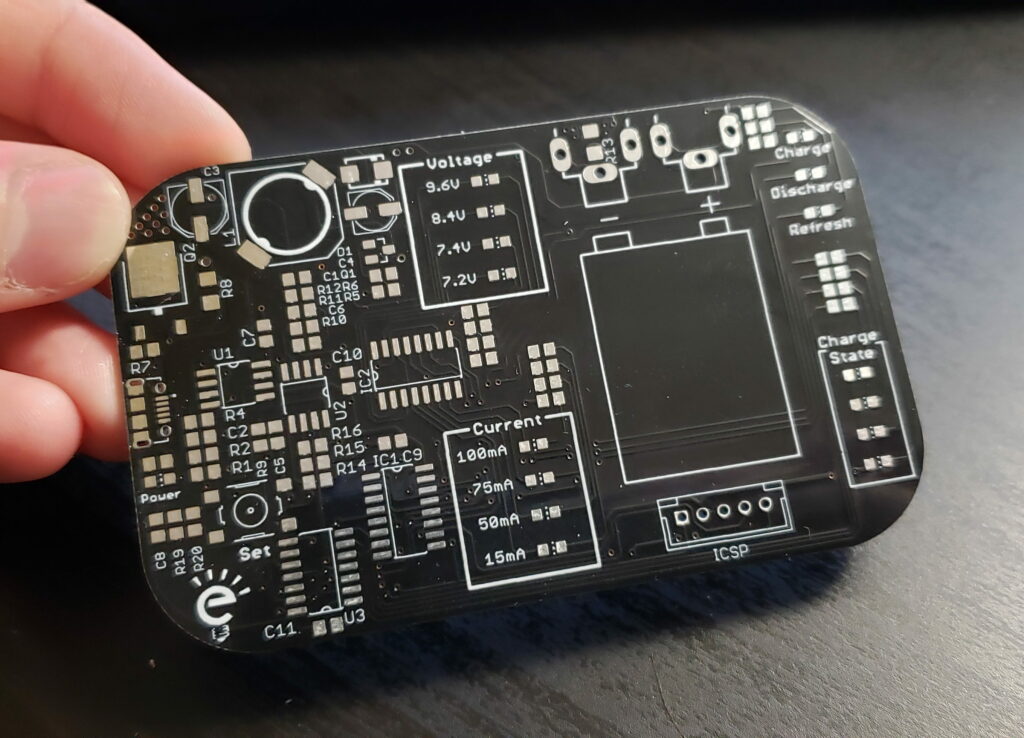
In a previous post, we’ve talked about how we were developing a better “9V” (PP3) battery charger and how it was based on an old project of mine. After about a week since the first prototype PCB was soldered up and ready for firmware development, we’ve released our latest product.
We were able to quickly build the firmware for the final version because most of the work was already done from the prototype that we had built last year, but that only got us so far. Most of the work this time wasn’t on the voltage/current regulation code, but instead was on the user interface, and on the actual detection of the charge/discharge status of the battery.
This is a pretty small product and something that is, in my opinion, quite different from what’s currently available on the market. I hope you enjoy it and consider purchasing one!
Back in May of 2015, a bit less than 6 years ago, I realized that there weren’t any good and practical charger for PP3 batteries (commonly known as 9V batteries), all of the products on the market are either those horrible wall chargers straight from the cheapest Chinese factories, more up-market models that either assumes the type of NiMH battery you’ll insert or just try to recharge them to the highest voltage possible with a lot of current limiting, or professional chargers aimed at the hobby market. None of these solutions worked for me. They ranged from “I would never trust to leave this charging while I sleep” to “that’s way too much hassle”, so I’ve decided that I could do better.
The first problem that we have to overcome is the fact that there are way too many different “9V” rechargeable batteries on the market. They all look exactly the same (of course), but their voltages greatly differ. Most of them are of the NiMH variety, but more recently lithium alternatives have come to market, although I haven’t had the chance to buy one to try out yet, I still prefer my good old NiMHs. So let’s look at what’s out on the market right now:
NiMH 7.2V (6 NiMH cells in series): These are quite old, and very rare these days. I guess it was the best way to get a relatively high capacity battery for more demanding applications back when they were introduced, but this came at the cost of having a very low nominal voltage, although most 9V appliances wouldn’t have any problems with this.
Li-Ion 7.4V (2 Li-Ion cells in series): The latest and probably the last version we’ll see of the 9V battery, sporting an amazing capacity thanks to that lithium magic, but suffers from a low nominal voltage, which as discussed previously might not be a big problem after all. The only issue I have with these is that I still don’t trust lithium to be left unattended discharging away in a device that might take the cells to quite low levels. NiMH cells are a lot easier to “heal” after they have been abused or neglected.
NiMH 8.4V (7 NiMH cells in series): The most popular type of rechargeable 9V battery. These strike a good balance between nominal voltage and capacity and are my preferred choice. Usually, if a battery isn’t labeled it’s almost a given that it’s an 8.4V model.
NiMH 9.6V (8 NiMH cells in series): If you need a pretty high nominal voltage and don’t care a lot about capacity this type is the way to go, just be mindful that most 9V hardware will gladly over-discharge them and ruin your day, so always keep an eye on their voltage from time to time.
As you can clearly see there are quite a lot of battery types out there (and some of them aren’t even marked!), so our charger must be able to handle them all, preferably without trying to be dumb smart and detecting the battery voltage. The user should be able to manually select the type of battery that they are inserting, but the software of the charger can also apply the classic dV/dt algorithm to determine when to terminate the charge if the user is unsure about the type of battery they got.
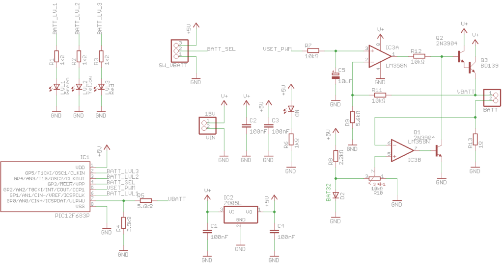
Since back then I just wanted to make something quick and only for me, I’ve designed a simple PIC12F683-based charger with a basic buffered op-amp linear CV/CC voltage regulator that fits inside an Altoids tin together with the battery that it was charging. This was a pretty neat solution, it would have a nice enclosure, I could have multiple charging a bunch of my batteries at the same time, and was very easy to write the code for. This was the schematic and board that I came up with:
First Concept Schematic
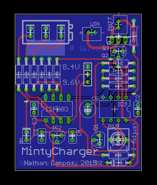
If you want to know more the GitHub repository is still up, but as you can see it’s a pretty simple board, and unfortunately due to size limitations it only was able to charge 8.4V and 9.6V batteries, which were most of my batteries back then, the charging current adjustment was manual with a potentiometer, and it required 15V to work. This was far from optimal, but I was in a hurry and it would perfectly fit my needs back then. Unfortunately because of the rise of the USD value and my lack of interest in the project I’ve never manufactured this board, and just continued charging my batteries with my lab power supply.
First Concept PCB Layout
Last year, while I was developing the Bipolary project, I was reminded of this long-forgotten project and decided to revisit it, use the knowledge that I’ve accumulated in the last 6 years, and redesign it completely from the ground up! Here are some of the features that I intend to implement in this new version:
5V USB power: Wall warts no longer an option, these days USB is the standard power outlet for almost everything. This also means I’ll have to use a switch-mode converter.
Capable of charging every single 9V battery out there: If I’m going to do this right, I’m going to support everything, even the lithium ones.
Neat design: Since I plan on selling these they must have a nice design and be easy to use.
Refresh batteries: Since these batteries usually live quite a hard life, and are constantly over-discharged, I think having a way to automatically try to bring them back to life is very important.
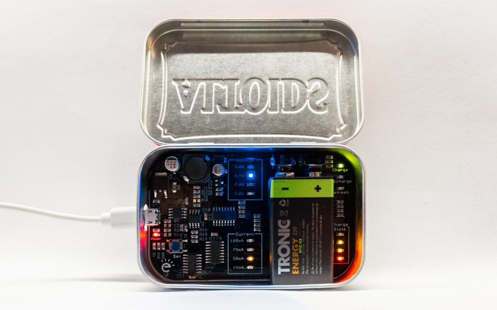
These were my goals when I’ve designed the circuit of this new version. Here’s a sneak peek:
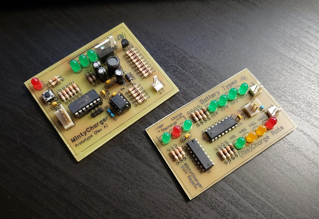
Manufactured PCB
Homemade Prototypes
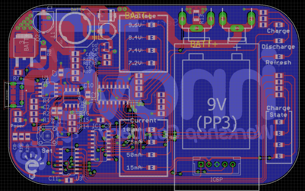
PCB Layout
Due to a whole bunch of reasons I’m only coming around to work on this project now, but I promise I’ll try my best to finish it quickly this time. I hope to post updates on it here pretty soon!
2 years ago me and my wife moved from Brazil to Portugal, but due to some unfortunate series of events we ended up having to live some months in a hotel while some construction work was being finished in our new apartment. Because of this I was without an electronics lab for way too long, which gave me more time to do some software projects. From these turbulent times a static blog generator was born. I’ve always wanted to write my blog posts in plain HTML, which gave me a lot more flexibility than Markdown, and this was the foundation for Levissimo, to be kind of the suckless of blogs.
As you might have noticed, I’ve imported some of my posts that I had on my old blog, Current Flow, which was originally a Tumblr that I converted to Levissimo, so if you want to see exactly how an instance of this blog generator is, that’s the place to go.
How a Levissimo Instance Looks Like
If you want to learn more about this project or maybe even try it out make sure to head over to the GitHub repository where you’ll find everything about it including how to set it up.
Unfortunately, as much as I was very eager to use Levissimo for the company blog, I’ve decided against it and went with WordPress for the simple reason that I wanted something that I could quickly set up and customize without having to waste much time programming, since my free time is quite scarce these days, but also because WordPress is so easy to migrate from, thanks to awesome first-party and third-party tools, that if I decide to migrate to Levissimo, it’s just a matter of exporting the data and writing a script to import all of it into Levissimo.
Finally I would like to add that even though Perl gets a lot of hate these days, it’s still one of the programming languages that I love most, and continue to cling to whenever a project comes up where it will be useful. If you come to it with an open mind, stick to Modern Perl, and doesn’t despise sigils, you might end up loving it as well.
If you’ve ever had an Apple computer or has worked with someone that uses one you’re more than likely familiar with the infamous .DS_Store, .Trashes, and other files that macOS leaves absolutely everyone. These files are akin to Thumbs.db, and desktop.ini on Windows, they are used by the operating system as either cache, temporary/special storage, or as a way to store special attributes that are not natively supported by the underlying filesystem. They are, for the most part, completely optional, and shouldn’t be hanging around your file server, littering your folders and causing confusion. Thankfully deleting and blocking these files from being created is quite a trivial task under Windows Server if you have the File Server Resource Manager role installed.
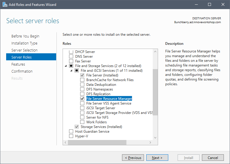
Before we begin, make sure that you have the FSRM role installed in your file server by going to the Server Manager and selecting the File and Storage Services > File and iSCSI Services > File Server Resource Manager role from the Add Roles and Features Wizard like this:
Installing FSRM role using the GUI
Alternatively if you’re running Windows Server Core, like I am in this case, you can install this role by running the following PowerShell command:
After you have everything installed and properly setup let’s focus our attention to the files that we want to block/remove from our network shares. The most common ones that are created by macOS are:
._*
.DS_Store
.Trashes (Directory)
.TemporaryItems (Directory)
.apdisk
All of these files are completely optional and can be blocked from being created without any problems to the users of your network shares. From here you can block the files from this list using the GUI or PowerShell by following this tutorial from Microsoft or, since this is quite a tedious task, run my PowerShell script to setup all of the file screening rules and delete any of these files that are already in your network shares. This way you can easily set this up even on Server Core installations, which is the case of my file server.
# Block-FsrmMacJunk.ps1
# Sets up file screens to block junk files from Mac OS from your network shares.
#
# Author: Nathan Campos

# Variables
$MacJunkPatterns = @("._*", "*.DS_Store", "*._.DS_Store", "*.Trashes",
    "*.apdisk", "*.TemporaryItems")

<#
.SYNOPSIS
Comfirms an action with the user.

.PARAMETER Message
Message that will be shown for the user to accept or reject.

.OUTPUTS
True if the user confirmed the action.
#>
Function Confirm-WithUser {
    Param(
        [Parameter(Mandatory = $true)]
        [String]$Message
    )

    $Response = Read-Host -Prompt "$Message [y/n]"
    While ($Response -NotMatch "[YyNn]") {
        $Response = Read-Host -Prompt "$Message [y/n]"
    }

    Return $Response -Match "[Yy]"
}

<#
.SYNOPSIS
Creates the file group describing all the junk files a Mac can place on a file system.

.DESCRIPTION
Creates the file group describing all the junk files a Mac can place on a file system.

.INPUTS
None.

.OUTPUTS
Nothing.

.LINK
New-FsrmFileGroup
#>
Function New-MacJunkFileGroup {
    Write-Output "Creating junk Mac files file group..."
    New-FsrmFileGroup -Name "Mac Files" -IncludePattern $MacJunkPatterns | Out-Null
}

<#
.SYNOPSIS
Creates the file screen template to block all the junk files from Macs.

.DESCRIPTION
Creates the file screen template to block all the junk files from Macs.

.INPUTS
None.

.OUTPUTS
Nothing.

.LINK
New-FsrmFileScreenTemplate

.LINK
New-MacJunkFileGroup
#>
Function New-MacJunkFileScreenTemplate {
    Write-Output "Creating junk Mac files file screen template..."
    New-FsrmFileScreenTemplate -Name "Block Mac Junk Files" -IncludeGroup "Mac Files" `
        -Active | Out-Null
}

<#
.SYNOPSIS
Creates the file screen to block all the junk files from Macs in a particular directory.

.DESCRIPTION
Creates the file screen to block all the junk files from Macs in a particular directory.

.PARAMETER Path
Path of the directory that you want to screen for Mac junk.

.INPUTS
Path of the directory that you want to screen for Mac junk.

.OUTPUTS
Nothing.

.LINK
New-FsrmFileScreen

.LINK
New-MacJunkFileScreenTemplate
#>
Function New-MacJunkFileScreen {
    [CmdletBinding()]
    Param(
        [Parameter(ValueFromPipeline, Position = 0, Mandatory = $true)]
        [String]$Path
    )

    Write-Output "Creating junk Mac files screen in `"$Path`"..."
    New-FsrmFileScreen -Path $Path -Template "Block Mac Junk Files" -Active | Out-Null
}

# Check for the required arguments.
If ($args.Count -lt 1) {
    Write-Error "No directory to create the Mac junk file screen was passed to the script."
    Write-Output "Usage: Block-FsrmMacJunk "
    Write-Output
    Write-Output "    PathToScreen    Path of the directory that you want to screen for Mac junk."
    Exit
}
$SharePath = $args[0]

# Create everything needed for the file screen.
New-MacJunkFileGroup
New-MacJunkFileScreenTemplate
New-MacJunkFileScreen $SharePath

# Delete any existing Mac junk.
If (Confirm-WithUser "Do you want to delete the Mac junk files that are already in the directory?") {
    Write-Output "Deleting all of the Mac junk for your network share..."
    Get-ChildItem -Path $SharePath -Include $MacJunkPatterns -Recurse -Force | Remove-Item -Force
}

Write-Output "All done!"
When you run this script please remember to specify the network share that you want to setup the file screening in (e.g. .\Block-FsrmMacJunk.ps1 E:\Shares), but don’t worry that the script will throw an error and remind you of this in case you forget. The script will also ask if you want to delete any of these files that might already be in your network shares.
For a long while I’ve been thinking about creating a blog for the company, a place where I can write about things that are happening, share some quick tips and tricks that I’ve learned from a current project, and post updates on what we are currently up to.
After wasting quite a lot of time figuring out how WordPress themes work in order to make it fit with our website’s current theme, I’m happy to announce that we finally have the blog up and running!
This blog won’t be dedicated to anything in particular, basically if something is happening in the workshop and I feel like sharing, it’ll be posted here, so expect some interesting content to come out in the near future!
Currently I’m extremely busy and making some changes to the website in order to accommodate a portfolio of my projects that I’ve made in the past, or products that are not currently for sale, so it might take a while until I make another post.
This post was imported from my old blog Current Flow.
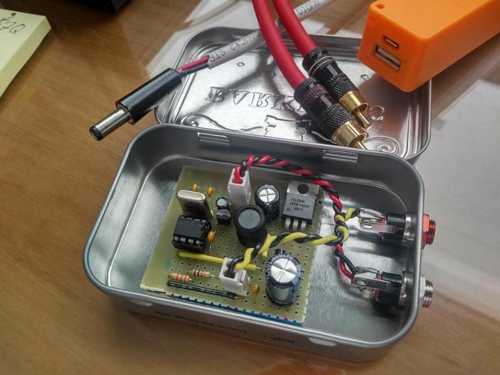
Finished project
First of all a bit of a back story: This is my first attempt at a DC-DC converter, I’ve always thought they were magic black-boxes that you just had to accept and building one yourself without a dedicated chip was something extremely difficult, something that could only be done with some high-speed complex analog circuitry or high-speed microcontrollers. I think a lot of people think the same way and I decided to try out my luck and it worked fine, switch-mode converters are not black magic (now only RF is black magic), and I hope I demystify them for you too in this article.
The idea for this project came because I built a nice portable Class-A headphone amplifier (blog post coming in the future) and I wanted a simple power supply for it when I was using it with my computer, so I had to step the 5V from the USB to the 9V required by the amplifier circuit, the amplifier even though it’s Class-A has a low current consumption, so the 2.5W from a normal USB was more than enough. Taking into consideration all this I needed a boost converter with the following specs:
5V input at 450mA maximum to work with any USB port
9V output able to source up to 110mA (more than enough for my amp)
Acceptable voltage ripple and noise since this will be used with pre-amps and the headphone amp
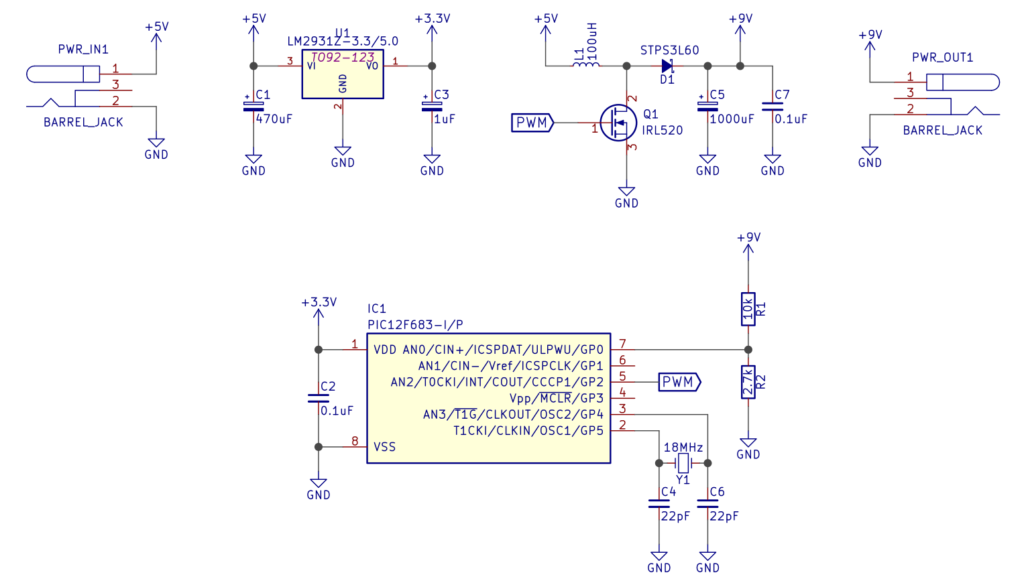
Circuit Schematic
As you can see there’s not a lot happening, and that’s the beauty of this design, since it was made for low power projects it doesn’t require any of the complexities, it was designed to be minimalistic and easy to build for someone that is new to switch-mode converters. The entire feedback control loop is contained inside the PIC12F683 microcontroller, it is a pretty tiny and under-powered micro, but as you will see it works perfectly for this task.
First the power input goes through a 3.3V regulator which provides power to the PIC and also acts as a voltage reference, then the microcontroller takes control of things and starts the PWM, pulsing current through the main inductor L1 while sensing the output voltage, if the voltage is lower than the set voltage it increases the PWM duty cycle, if the voltage is higher than the set voltage it decreases the PWM duty cycle, and that’s all you need to create a simple switch-mode converter. Here’s the code that runs the whole thing (I still need to improve it, so changes are coming):
If you’re a bit more experienced with DC-DC converters you’ll notice that the components used are a bit overkill, but that’s by design because I wanted very low ripple at the output, also in the topic of components, I selected a IRL520 MOSFET and this is very important, since I’m driving the gate with very low voltages a logic-level MOSFET is a must, if you want to use a regular MOSFET you’ll have to increase the gate voltage using a technique shown here.
A very handy tool for everyone designing their own DC-DC converters is Adafruit’s DIY DC-DC Boost Calculator, it was extremely useful to choose the components used in this project and it’ll surely help you in yours too. I’ve also written a R script to have a offline version of the calculator, it’ll be improved in the future, but it’s usable right now.
The only issue that I’m having with this project so far is the fact that no matter what I try, I can’t get the crystal to oscillate, I checked everything, set all the registers correctly and I still can’t get it to work, if anyone wants to help it’ll be greatly appreciated.
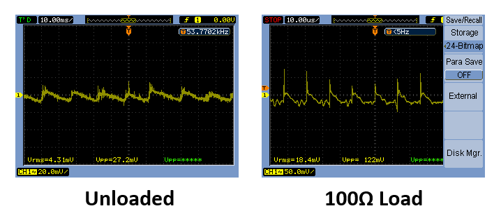
Noise figures
Since all my designs have a lot of local decoupling to keep any noise or ripple from the power source away from sensitive parts I didn’t care too much about having extremely low ripple/noise, but if you want to upgrade this you can add a small shunt regulator to really kill any ripple or just add a LC filter to the output.
If you’ve got any questions feel free to ask and I’m open to suggestions for improvement.
This post was imported from my old blog Current Flow.
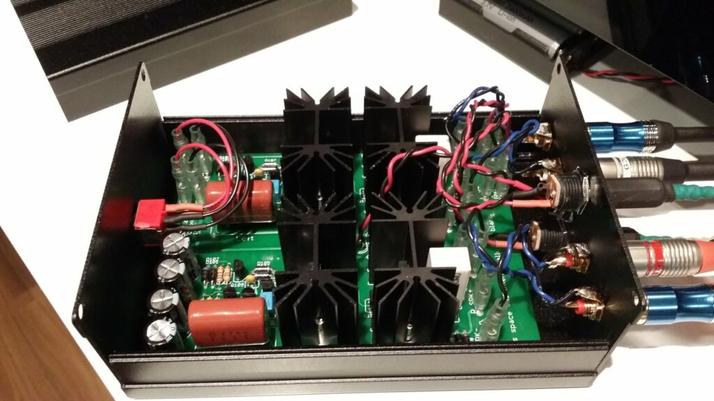
Amplifier with the lid open
I’m back with another amplifier project, but this time it’s kind of like a remake instead of a completely new amp. The story behind this project started 4 days after I completed the Mini6.
While I was drilling the holes for the jacks on the Mini6, I accidentally put too much pressure on the acrylic enclosure and it cracked, it was very small crack, practically impossible to see, between the two RCA jacks on the front, but after using it for a while and noticing how the crack would open a little bit every time I plugged something in, I decided to fix it using super glue (facepalm) and while I was using the glue I didn’t notice that one small drop fell in the PCB. I put everything back together and tested, it sounded horrible and when I looked inside I could see the stain of the glue which was destroying the sensitive part of the circuit. So in a moment of rage I decided to throw the whole amp in the trash and design a better one and put it in a better enclosure. So that’s how the Power12 was born.
Circuit Schematic
The first thing I did to the original design was add a Zobel network to increase the stability of the amplifier. The other modification I did was the addition of a active load in the gain stage. Sadly when I was designing it I forgot to add another active load for the differential pair, but this will be fixed in the next revision of the board (I’ll also add a SIM).
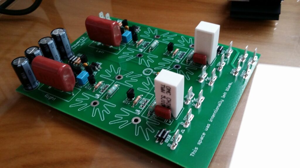
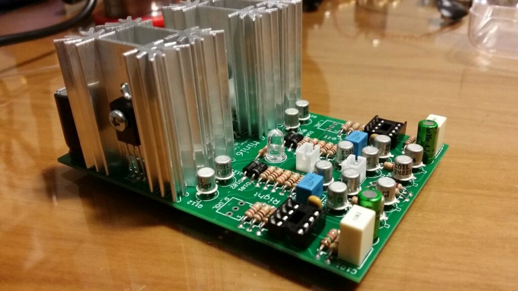
Circuit without the heatsinks are power devices
Populating the board was a pretty straight forward process since there aren’t a lot of components to be placed and as usual the most difficult part was soldering the spade terminals to the ground plane.
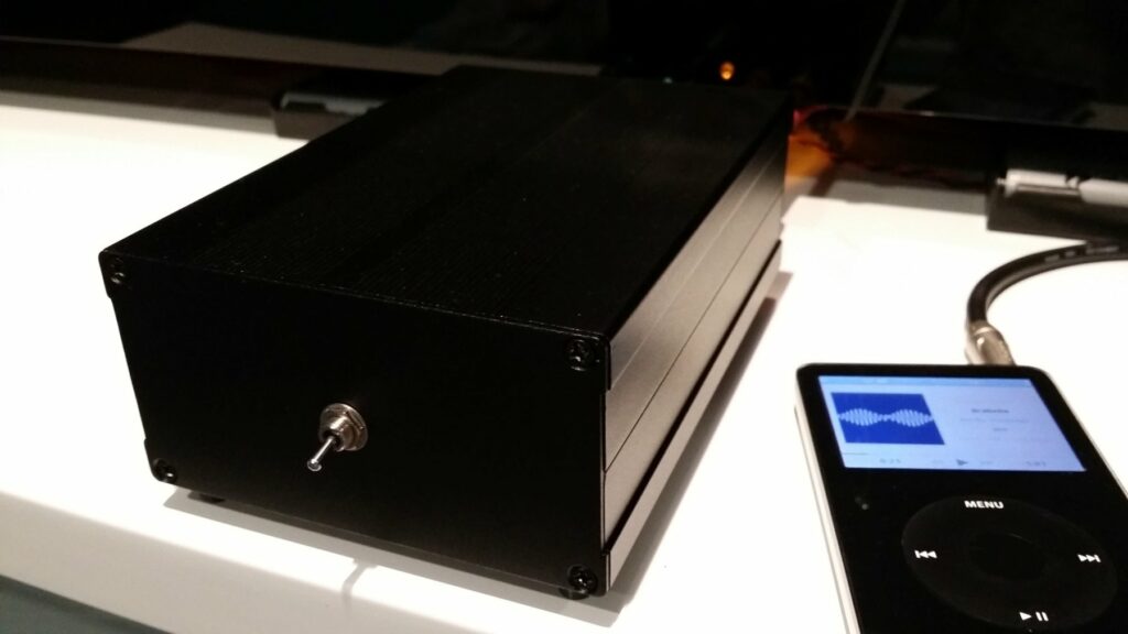
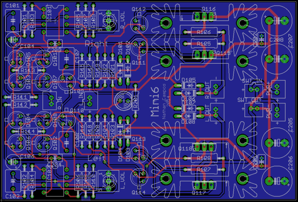
Finished enclosure
This time I decided to use a very nice extruded aluminium enclosure that I found on AliExpress. I was a bit skeptical at first about the quality of the enclosures, but when they arrived I was surprised how beautiful they were, and the quality of the extrusion was really good. The seller was great, emailed me to ask about the customs, shipped extremely fast, and packed everything extremely well to make sure nothing would scratch the very fragile black paint of the case and the panels.
Since I decided to use a aluminum enclosure, the best combination would be a very minimalist design, so the only thing in the front panel is the power switch. This decision gave me the idea to place the power LED on the back, giving it a really cool look when it’s powered on.
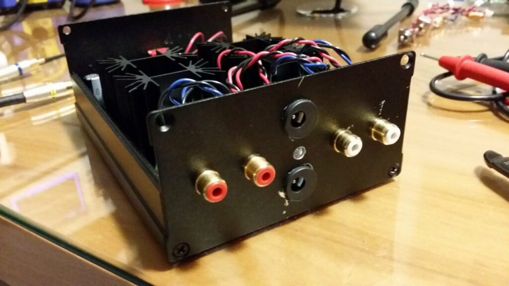
Back panel
Drilling the holes for the 2.1mm power connectors was a pain in the ass since I didn’t have a drill bit that was bigger than 8mm, so I was forced to use the “wiggle” technique to make the holes bigger and because of that the drill bit escaped the hole a couple of times and damaged a bit of the back plate, but since it’s on the back no one will ever see my mistakes.
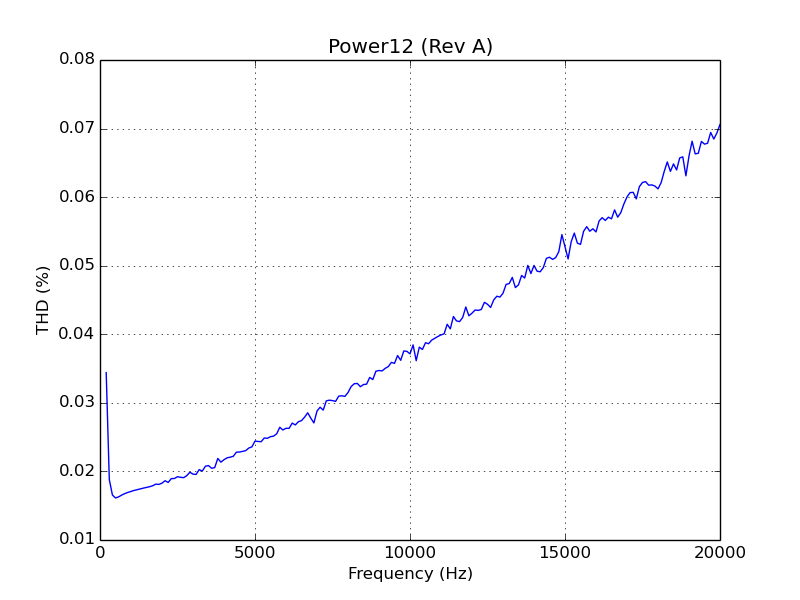
THD values from simulation
The distortion figures are not the best you’ve probably seen (it’ll be a lot better when I add the second active load in Rev B), but it’s low enough that you won’t be able to notice it. The plot was created using a script I’ve created called plot_thd.py, running this SPICE circuit. Sadly I don’t have the equipment to measure the real figures, but I’m planning to buy a Keithley 2015 next month.
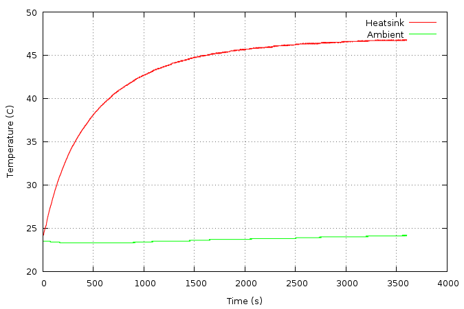
Temperature of the heatsinks
One thing that I actually was able to measure was the temperature profile of the amplifier, and as you can see it runs pretty cool with those FA-T220-38E heatsinks. Those figures were measured with the lid closed and with the amplifier right at the point of clipping with a 1kHz sine wave into a 8 ohm load. I’ve used my Agilent U1242B multimeter in conjunction with a program I wrote called dmmlog to grab the data, then plotcsv to generate the graph you see. Sadly I forgot to take pictures of the test setup.
If you want to see all the pictures of the project this Imgur album contains all of them. If you want to have access to all of the files related to this project check out the GitHub repo, and if you want to discuss it the best place to go would be the diyAudio thread.
This post was imported from my old blog Current Flow.
Finished project
I was a bit bored a couple of weeks ago so I decided to design a very simple discrete amplifier rated for 6W/channel just to make sure it wouldn’t oscillate and be more confident to build bigger ones.
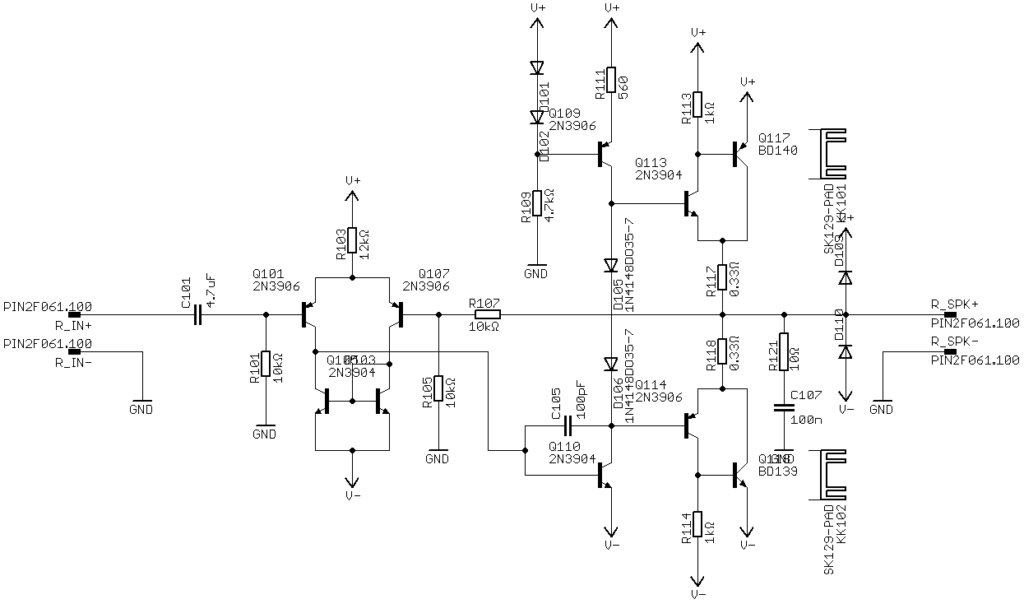
Circuit Schematic
As you can see it’s a fairly simple design with a op-amp pre-amplifier and a discrete power amplifier. Building it was extremely simple, the difficult part is always mounting all the panel components and wiring everything.
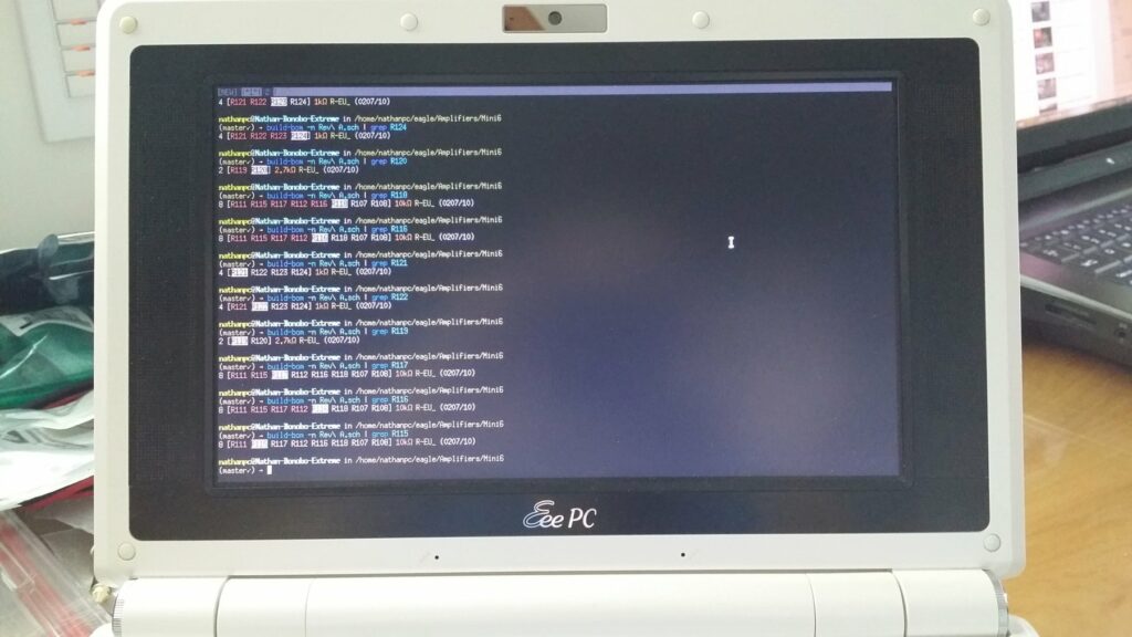
Using build-bom to make my life easier while soldering
A while ago I built a program called build-bom to help me quickly find the component values when assembling a board. It’s a great use for a old EeePC that you may have laying around.
Components all soldered
One thing that you may have noticed is that I’ve used canned transistors instead of your typical plastic TO-92. The only reason I did this was because they looked cool and I have a bunch laying around.
How the board looks like in CAD
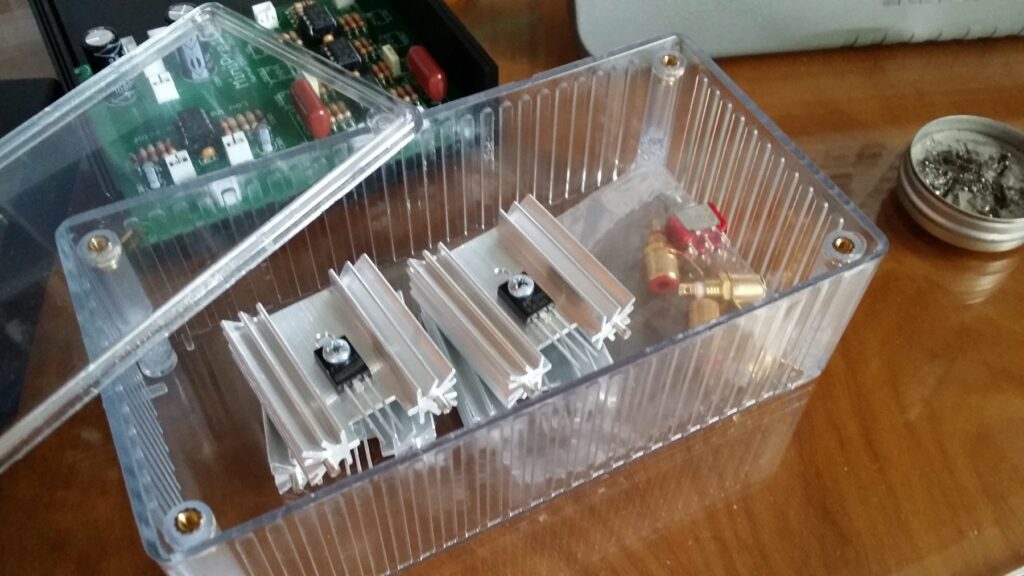
Organizing the components to begin soldering
Started soldering
Checking the values with my program
Top view of the board after soldering
Side view of the board
Board with the heatsinks
Front panel
Back panel
If you want to know more about the amplifier check out the GitHub repo.
This post was imported from my old blog Current Flow.
Update: This project was my first try at building an amplifier, because of this it is pretty awful in terms of performance, it has very noticeable crossover distortion. For better designs please look at newer posts here.
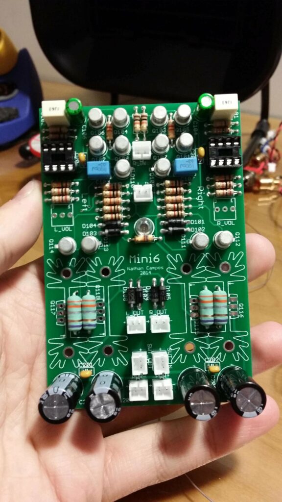
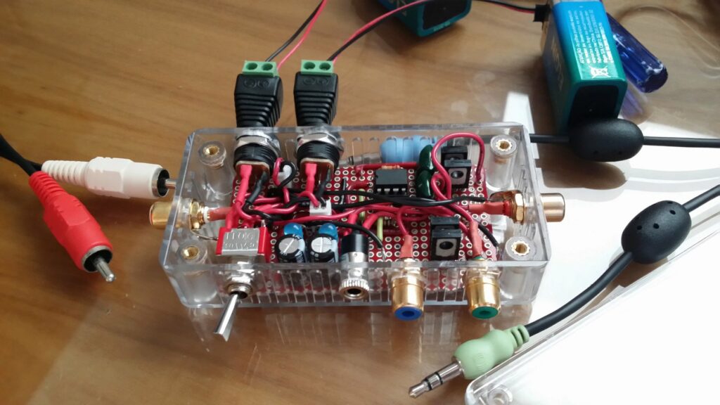
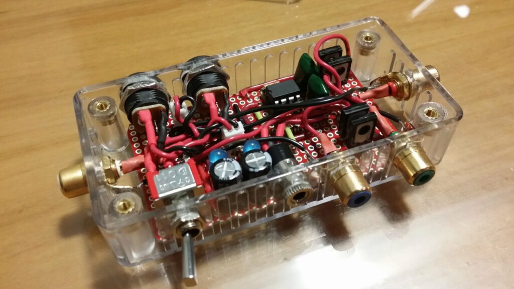
Finalized circuit
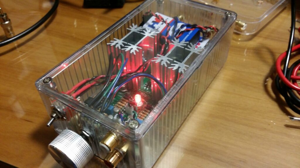
Last week, I decided to take on a very simple project: build a very low distortion, reasonably powerful, battery-powered amplifier that could fit in a very small, transparent enclosure that I had.
The main idea was to have this very small amplifier that could be moved around the house and powered from some 18650 cells so that I could enjoy some music with my friends when they come for our regular LAN parties. Usually we use one of those crappy iPod dock/speaker things that everyone loves, but, personally, they don’t sound very good to me.
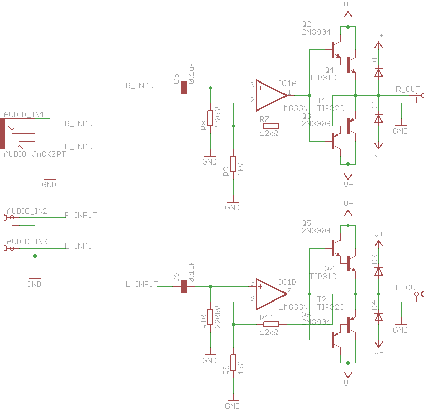
Since this was a quick project, I decided to make it as simple as possible to avoid any trouble. The easiest it could be was to use an audio op-amp driving a class B output made with Darlington transistors with some negative feedback to keep the distortion really low, so that’s what I did:
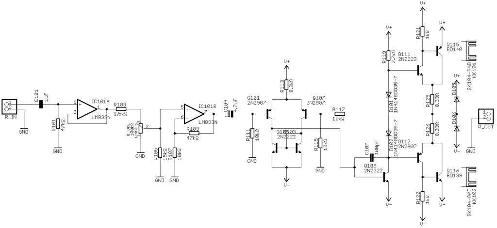
Circuit Schematic
I also designed a very simple peak detector to detect any clipping on the output to make sure the signal was as clean as possible, but, sadly, my case was so small that I couldn’t fit it in. Since it would be powered from 2 18650 packs (3 cells each) or a pair of 9V batteries, the power supply is extremely simplistic.
When all of the parts arrived, I decided to get everything prepared to be assembled the next day.
Parts ready to be assembled
Choosing where to put the jacks and switches was a bit tricky since the space inside the enclosure was extremely small.
Finished drilling all the holes for the connectors
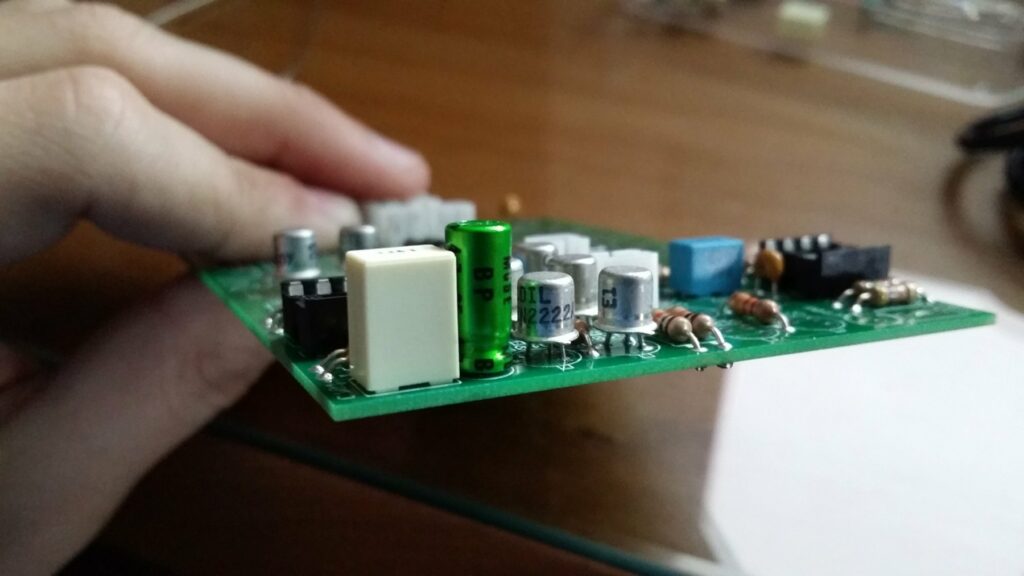
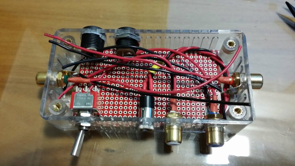
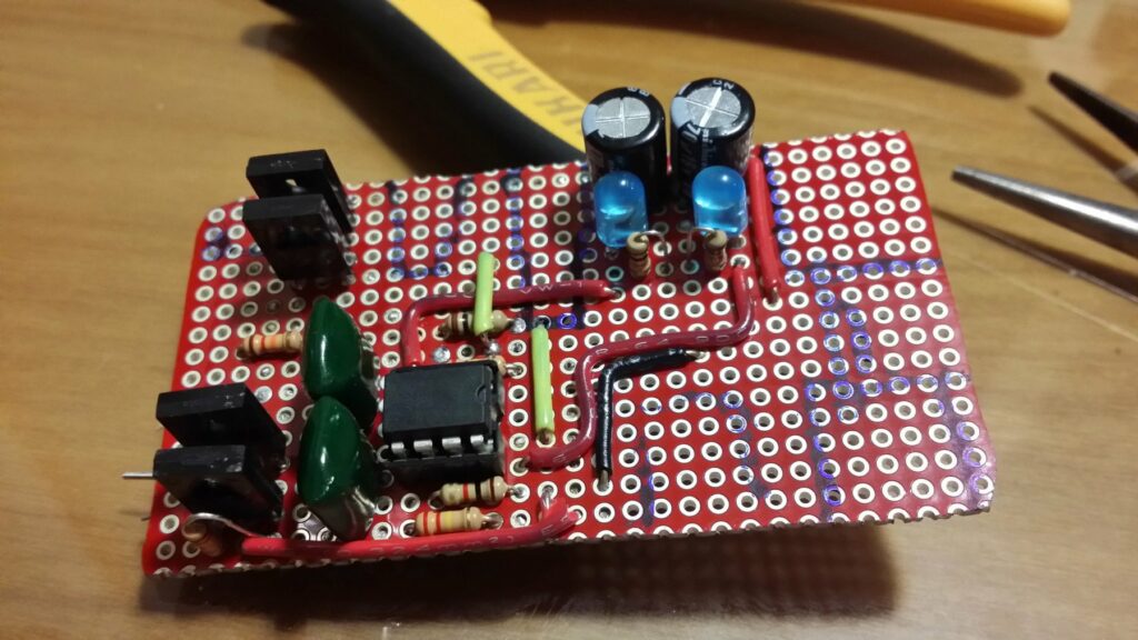
Since I wasn’t patient enough to wait for a PCB, I decided to build the whole thing on a piece of protoboard which was a bit tricky because of the space the jacks took.
Circuit all soldered up
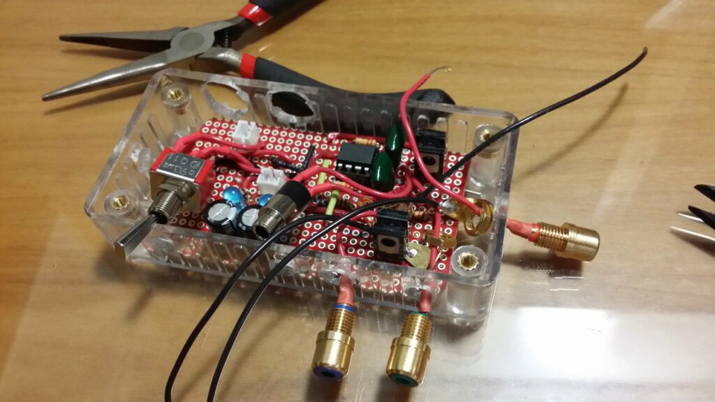
After soldering the headphone jack and on/off switch, mounted from the inside, it was time to solder the RCA jacks which had to be mounted from the outside. This was very difficult since I had to make the shortest cable possible while making sure that I could still lift the board up to solder the cable to the PCB.
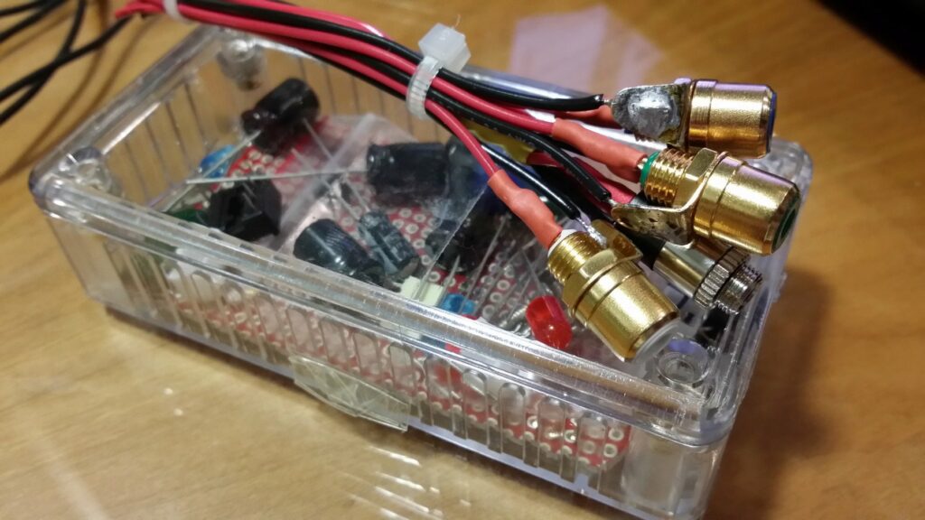
Soldering the connectors to the board
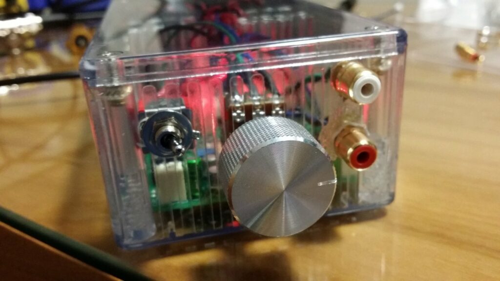
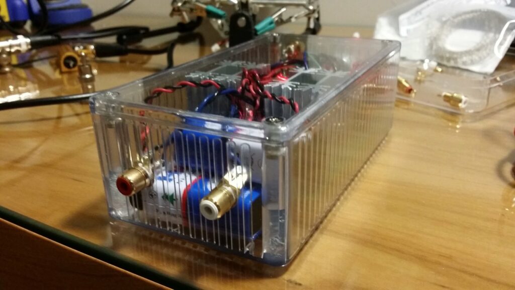
Sliding the board back into place was extremely difficult, but after a lot of wiggling, it was perfectly placed on the bottom of the enclosure, and I was ready to plug the power jacks into the JST connectors on the board. It was the only way to mount them, otherwise I wouldn’t be able to lift the board to solder them.
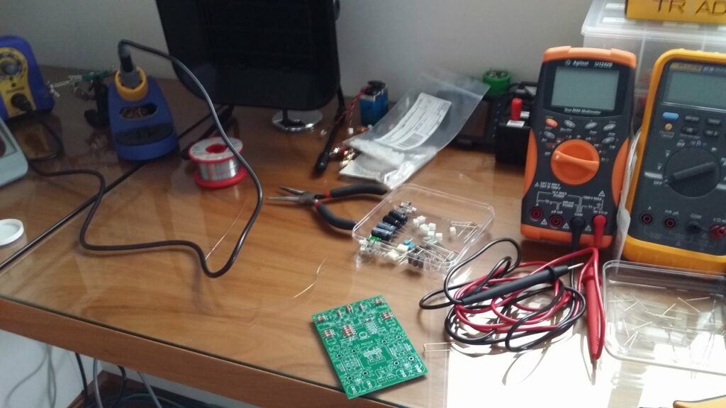
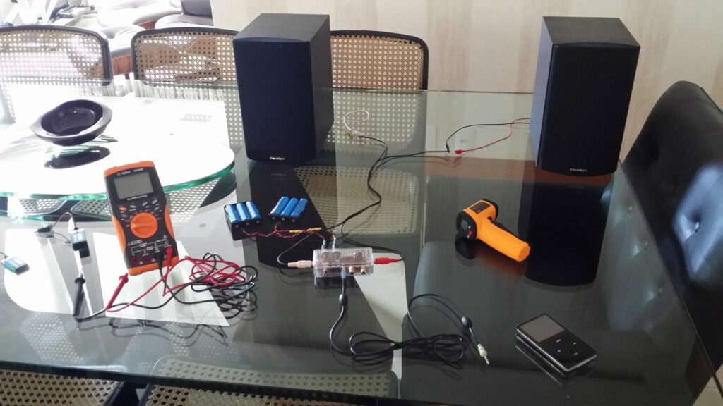
First thing to do in the morning was to test the little beast. This was the test setup (after using my oscilloscope and a dummy load to make sure everything was working fine). I had to use the living room table since my bench was a mess (as usual), and there was no space for the 2 speakers.
Testing the circuit in the living room
And that’s all! If you want more technical information about the project, be sure to visit the GitHub repo. If you want to discuss it, jump on over to the diyAudio thread.
This post was imported from my old blog Current Flow.
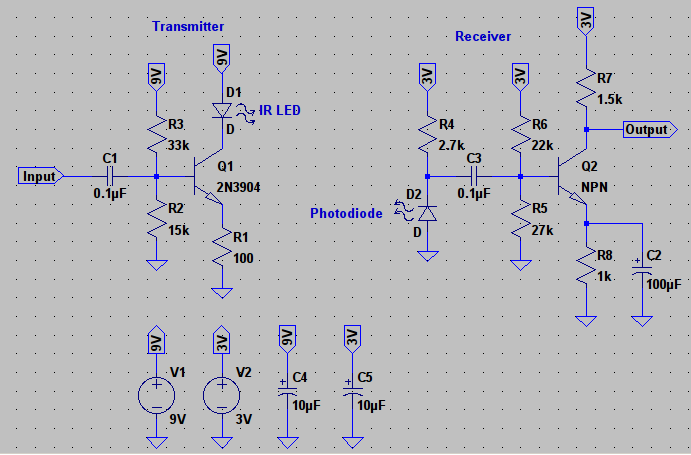
This week I’ve been experimenting with a very simple and cheap project for wireless transmissions, a lightwave AM transmitter and receiver based on Scott’s design, which was based on VK2ZAY’s design. In my final design I’ve increased the base biasing resistors to decrease the size of the coupling capacitor and also used a Darlington transistor to get more current gain.
Circuit Schematic in LTSpice
The transmitter is pretty straight forward, the input modulates the current passing by the LED, which modulates the intensity of light, if you’ve designed any class A amplifiers in the past you surely know how it works. The receiver is just a simple transimpedance amplifier, which is amplifying the signal quite a bit (~56x gain) since the transmitter will usually be a bit far from the receiver. You can do the same with a op-amp, but I much prefer a discrete circuit for these simple things.
You can put a buffer stage with a Darlington emitter follower on the output of the receiver so you can drive a speaker directly. Something that I would recommend is to add a small (10x gain maybe?) pre-amplifier for the transmitter, that way you’ll get a bit more signal if you’re source isn’t very loud, specially if you want to drive some high power LEDs, since you have a lot of current headroom with those.
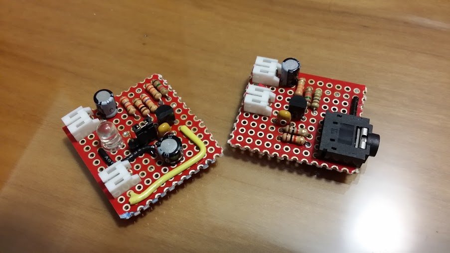
If you want to experiment with different values in a simulation, here is the LTspice schematic. The best way to choose the best LED + photodiode combination to maximize the range is to build some breakout boards that you can plug different LEDs and photodiodes until you have the perfect combination.
Prototypes all soldered up
We use cookies to ensure that we give you the best experience on our website. If you continue to use this site we will assume that you are happy with it.Ok