Audio


This post was imported from my old blog Current Flow.

Amplifier with the lid open

I’m back with another amplifier project, but this time it’s kind of like a remake instead of a completely new amp. The story behind this project started 4 days after I completed the Mini6.

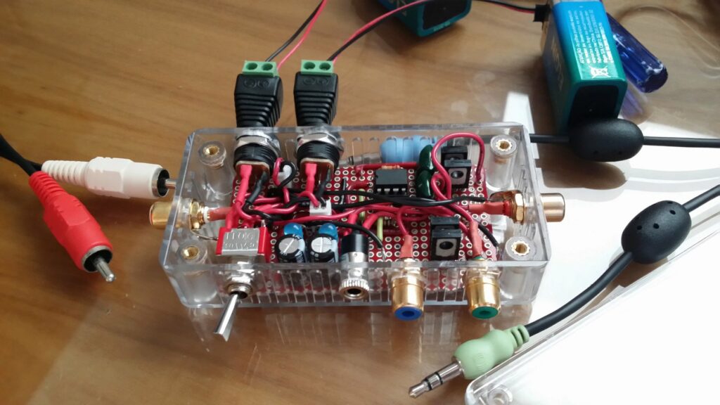
While I was drilling the holes for the jacks on the Mini6, I accidentally put too much pressure on the acrylic enclosure and it cracked, it was very small crack, practically impossible to see, between the two RCA jacks on the front, but after using it for a while and noticing how the crack would open a little bit every time I plugged something in, I decided to fix it using super glue (facepalm) and while I was using the glue I didn’t notice that one small drop fell in the PCB. I put everything back together and tested, it sounded horrible and when I looked inside I could see the stain of the glue which was destroying the sensitive part of the circuit. So in a moment of rage I decided to throw the whole amp in the trash and design a better one and put it in a better enclosure. So that’s how the Power12 was born.

Circuit Schematic

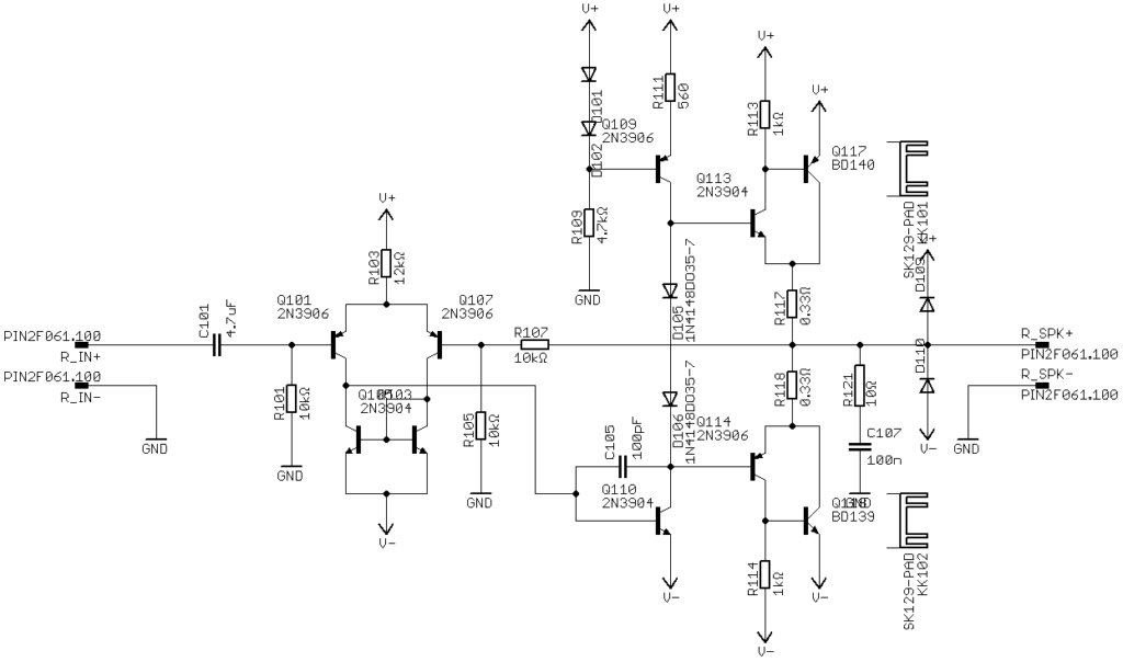
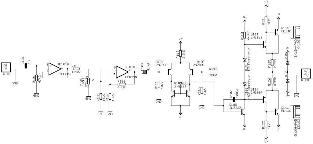
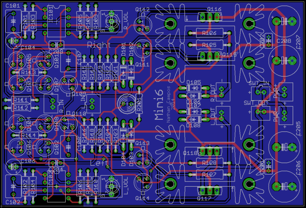
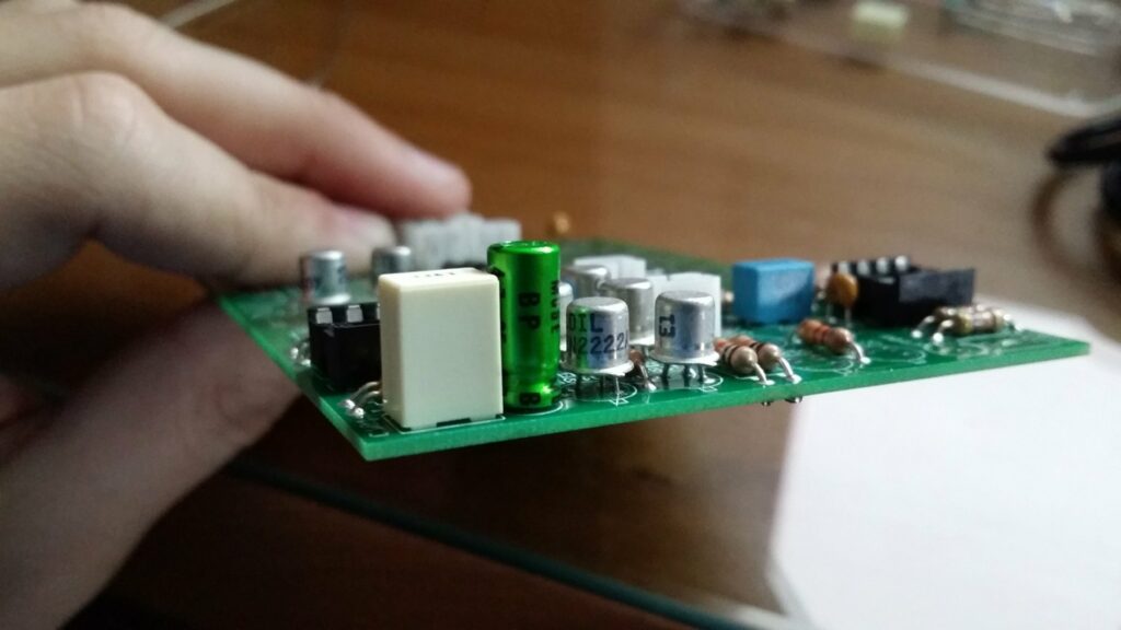
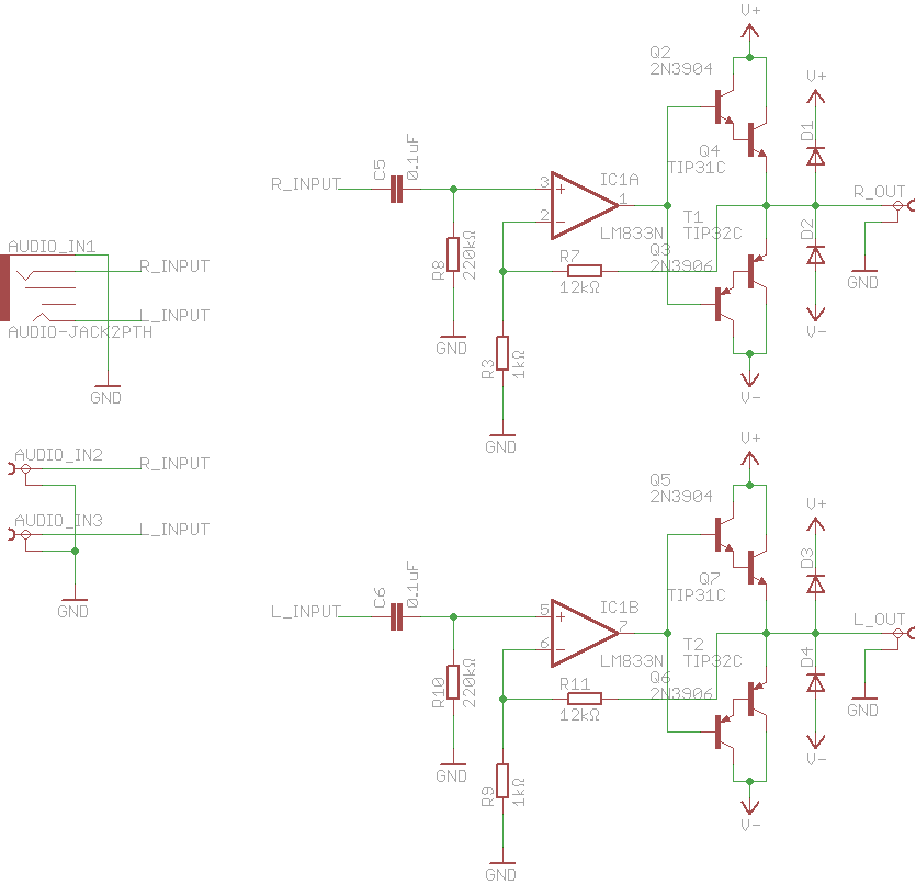
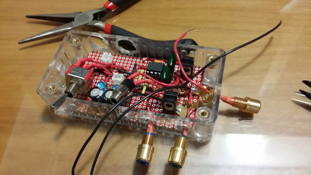
The first thing I did to the original design was add a Zobel network to increase the stability of the amplifier. The other modification I did was the addition of a active load in the gain stage. Sadly when I was designing it I forgot to add another active load for the differential pair, but this will be fixed in the next revision of the board (I’ll also add a SIM).

Circuit without the heatsinks are power devices

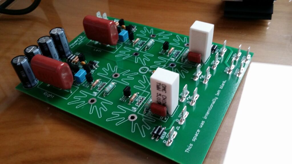
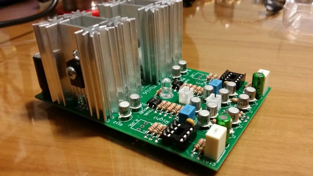
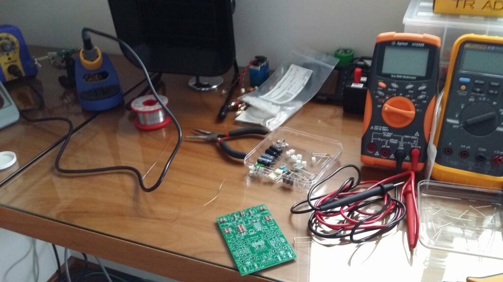
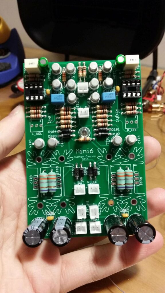
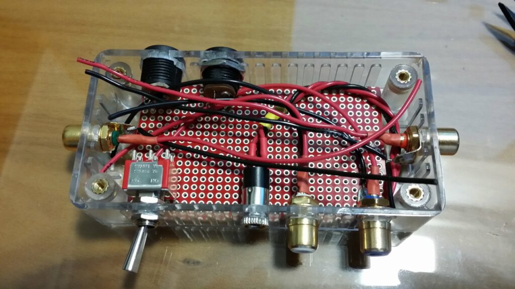
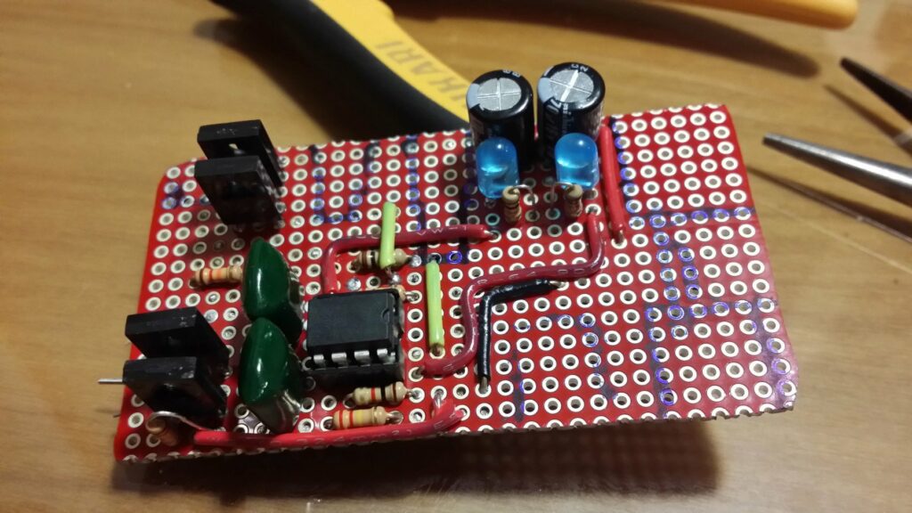
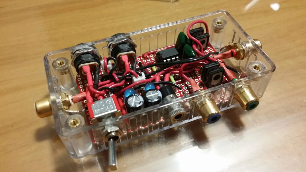
Populating the board was a pretty straight forward process since there aren’t a lot of components to be placed and as usual the most difficult part was soldering the spade terminals to the ground plane.

Finished enclosure

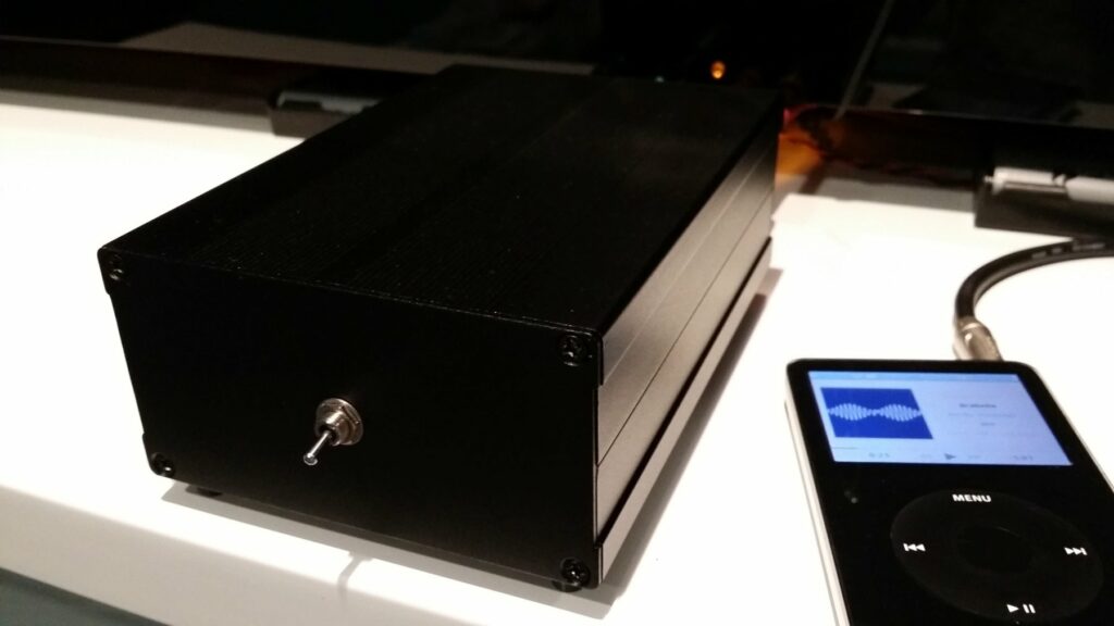
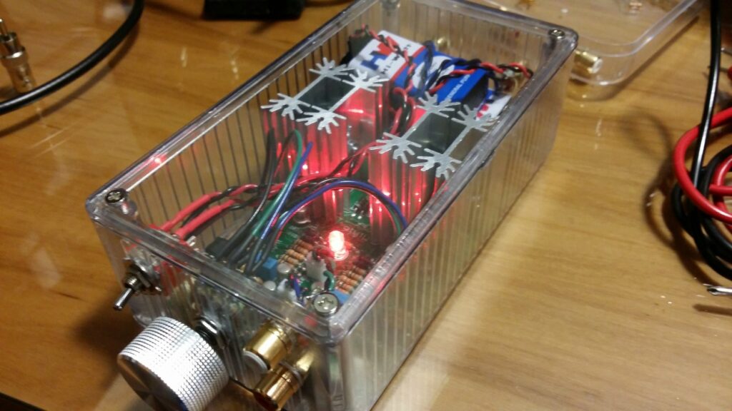
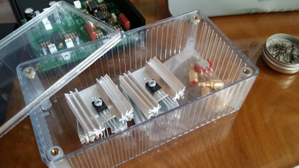
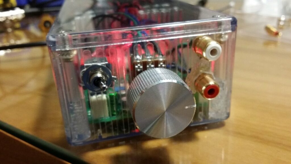
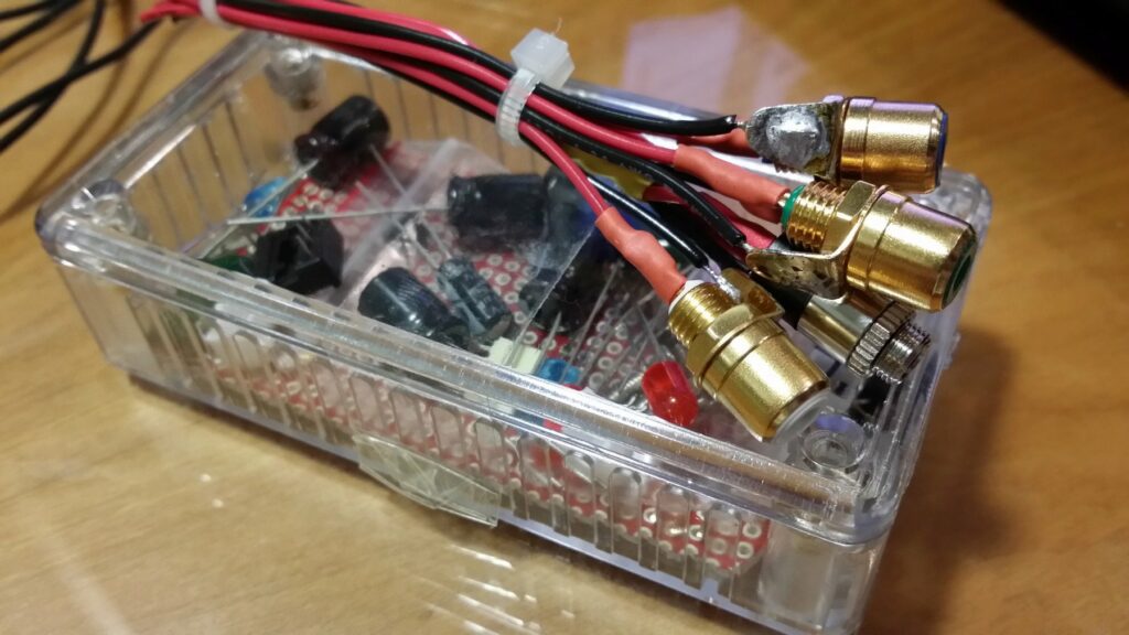
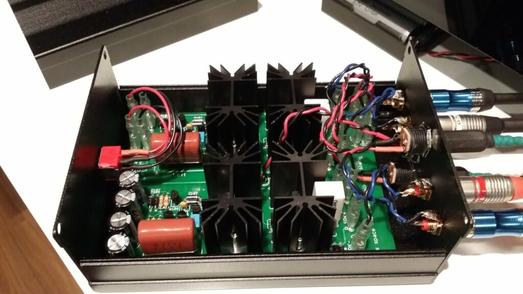
This time I decided to use a very nice extruded aluminium enclosure that I found on AliExpress. I was a bit skeptical at first about the quality of the enclosures, but when they arrived I was surprised how beautiful they were, and the quality of the extrusion was really good. The seller was great, emailed me to ask about the customs, shipped extremely fast, and packed everything extremely well to make sure nothing would scratch the very fragile black paint of the case and the panels.

Since I decided to use a aluminum enclosure, the best combination would be a very minimalist design, so the only thing in the front panel is the power switch. This decision gave me the idea to place the power LED on the back, giving it a really cool look when it’s powered on.

Back panel

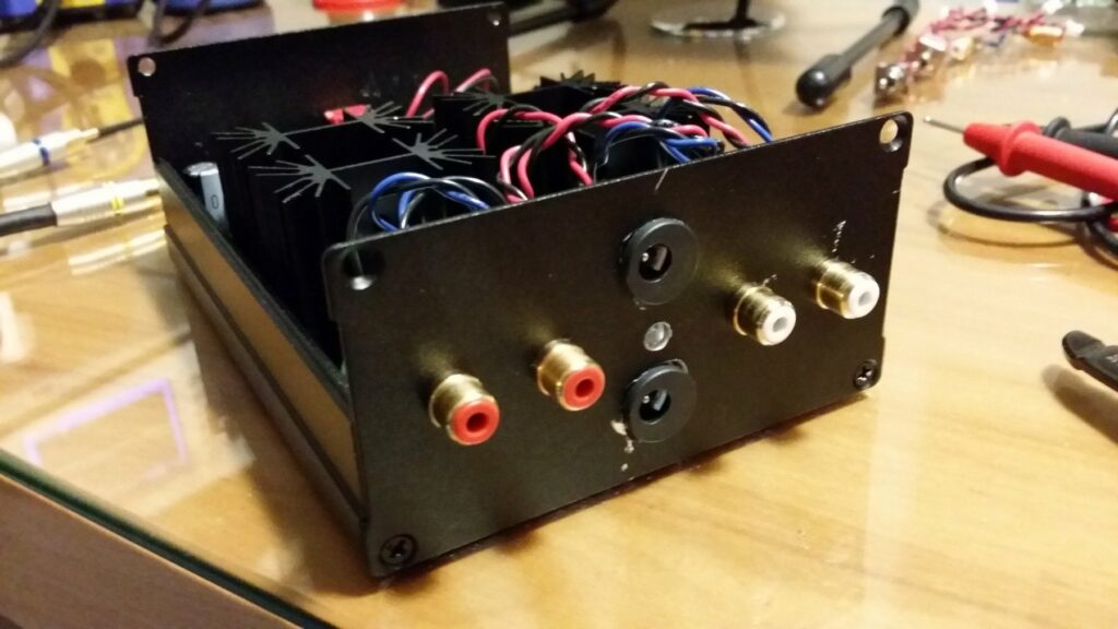
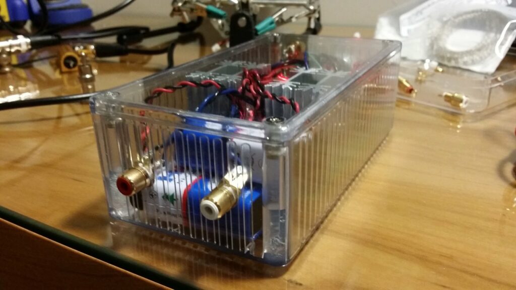
Drilling the holes for the 2.1mm power connectors was a pain in the ass since I didn’t have a drill bit that was bigger than 8mm, so I was forced to use the “wiggle” technique to make the holes bigger and because of that the drill bit escaped the hole a couple of times and damaged a bit of the back plate, but since it’s on the back no one will ever see my mistakes.

THD values from simulation

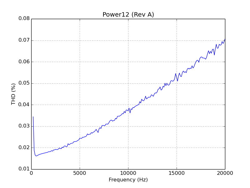
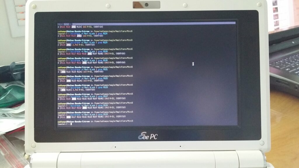
The distortion figures are not the best you’ve probably seen (it’ll be a lot better when I add the second active load in Rev B), but it’s low enough that you won’t be able to notice it. The plot was created using a script I’ve created called plot_thd.py, running this SPICE circuit. Sadly I don’t have the equipment to measure the real figures, but I’m planning to buy a Keithley 2015 next month.

Temperature of the heatsinks

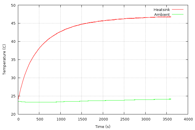
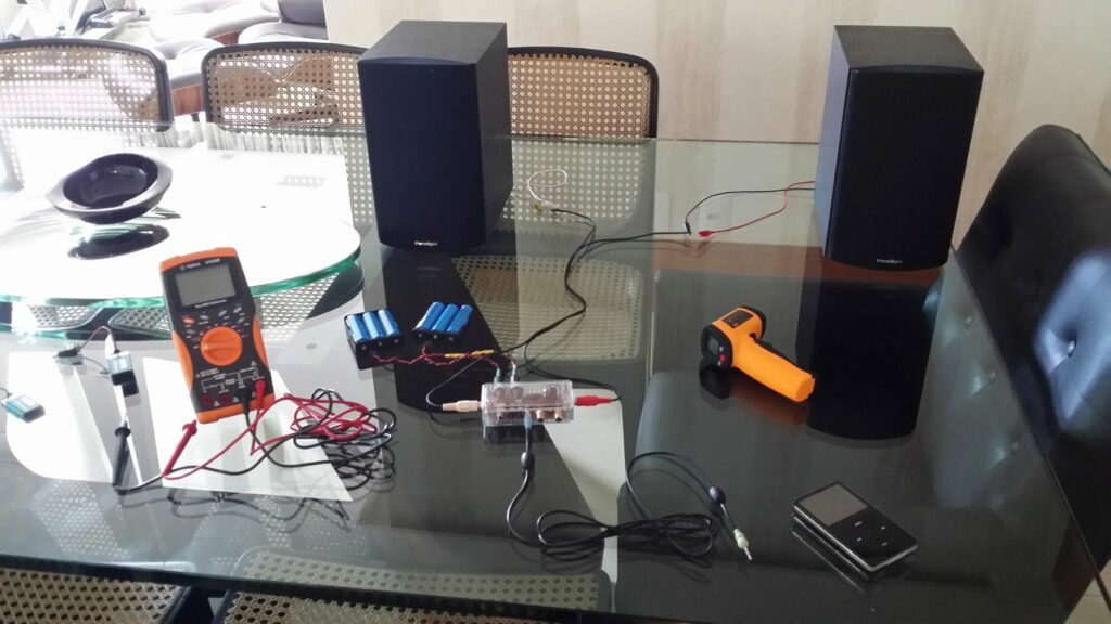
One thing that I actually was able to measure was the temperature profile of the amplifier, and as you can see it runs pretty cool with those FA-T220-38E heatsinks. Those figures were measured with the lid closed and with the amplifier right at the point of clipping with a 1kHz sine wave into a 8 ohm load. I’ve used my Agilent U1242B multimeter in conjunction with a program I wrote called dmmlog to grab the data, then plotcsv to generate the graph you see. Sadly I forgot to take pictures of the test setup.

If you want to see all the pictures of the project this Imgur album contains all of them. If you want to have access to all of the files related to this project check out the GitHub repo, and if you want to discuss it the best place to go would be the diyAudio thread.


Mini6 Amplifier


This post was imported from my old blog Current Flow.

Finished project

I was a bit bored a couple of weeks ago so I decided to design a very simple discrete amplifier rated for 6W/channel just to make sure it wouldn’t oscillate and be more confident to build bigger ones.

Circuit Schematic

As you can see it’s a fairly simple design with a op-amp pre-amplifier and a discrete power amplifier. Building it was extremely simple, the difficult part is always mounting all the panel components and wiring everything.

Using build-bom to make my life easier while soldering

A while ago I built a program called build-bom to help me quickly find the component values when assembling a board. It’s a great use for a old EeePC that you may have laying around.

Components all soldered

One thing that you may have noticed is that I’ve used canned transistors instead of your typical plastic TO-92. The only reason I did this was because they looked cool and I have a bunch laying around.

If you want to know more about the amplifier check out the GitHub repo.


This post was imported from my old blog Current Flow.

Update: This project was my first try at building an amplifier, because of this it is pretty awful in terms of performance, it has very noticeable crossover distortion. For better designs please look at newer posts here.

Finalized circuit

Last week, I decided to take on a very simple project: build a very low distortion, reasonably powerful, battery-powered amplifier that could fit in a very small, transparent enclosure that I had.

The main idea was to have this very small amplifier that could be moved around the house and powered from some 18650 cells so that I could enjoy some music with my friends when they come for our regular LAN parties. Usually we use one of those crappy iPod dock/speaker things that everyone loves, but, personally, they don’t sound very good to me.

Since this was a quick project, I decided to make it as simple as possible to avoid any trouble. The easiest it could be was to use an audio op-amp driving a class B output made with Darlington transistors with some negative feedback to keep the distortion really low, so that’s what I did:

Circuit Schematic

I also designed a very simple peak detector to detect any clipping on the output to make sure the signal was as clean as possible, but, sadly, my case was so small that I couldn’t fit it in. Since it would be powered from 2 18650 packs (3 cells each) or a pair of 9V batteries, the power supply is extremely simplistic.

When all of the parts arrived, I decided to get everything prepared to be assembled the next day.

Parts ready to be assembled

Choosing where to put the jacks and switches was a bit tricky since the space inside the enclosure was extremely small.

Finished drilling all the holes for the connectors

Since I wasn’t patient enough to wait for a PCB, I decided to build the whole thing on a piece of protoboard which was a bit tricky because of the space the jacks took.

Circuit all soldered up

After soldering the headphone jack and on/off switch, mounted from the inside, it was time to solder the RCA jacks which had to be mounted from the outside. This was very difficult since I had to make the shortest cable possible while making sure that I could still lift the board up to solder the cable to the PCB.

Soldering the connectors to the board

Sliding the board back into place was extremely difficult, but after a lot of wiggling, it was perfectly placed on the bottom of the enclosure, and I was ready to plug the power jacks into the JST connectors on the board. It was the only way to mount them, otherwise I wouldn’t be able to lift the board to solder them.

Completed project

Since it was 1:38AM, I was quite tired, and since I had been working on this thing for 7 hours and 12 minutes, I decided that it was time to sleep and leave the enclosure closing and testing for the next day. (Obligatory picture of the pile of wires and component leads)

First thing to do in the morning was to test the little beast. This was the test setup (after using my oscilloscope and a dummy load to make sure everything was working fine). I had to use the living room table since my bench was a mess (as usual), and there was no space for the 2 speakers.

Testing the circuit in the living room

And that’s all! If you want more technical information about the project, be sure to visit the GitHub repo. If you want to discuss it, jump on over to the diyAudio thread.