CurrentFlow


This post was imported from my old blog Current Flow.

Finished project

First of all a bit of a back story: This is my first attempt at a DC-DC converter, I’ve always thought they were magic black-boxes that you just had to accept and building one yourself without a dedicated chip was something extremely difficult, something that could only be done with some high-speed complex analog circuitry or high-speed microcontrollers. I think a lot of people think the same way and I decided to try out my luck and it worked fine, switch-mode converters are not black magic (now only RF is black magic), and I hope I demystify them for you too in this article.

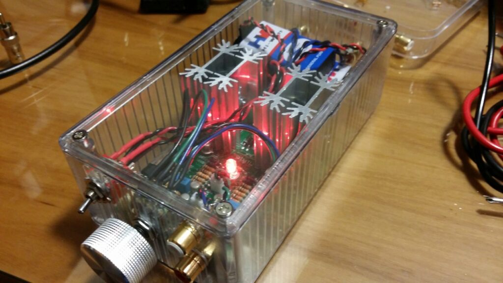
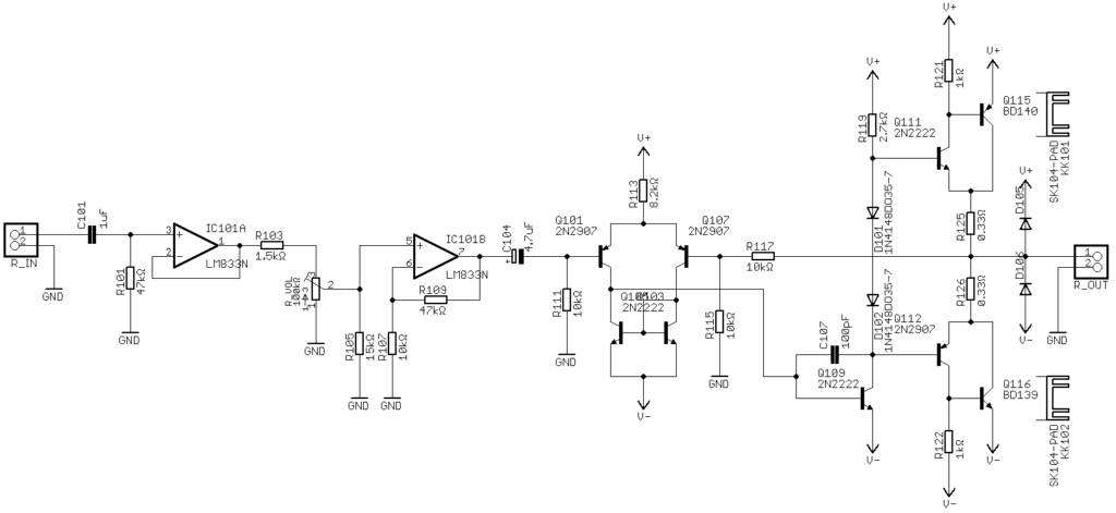
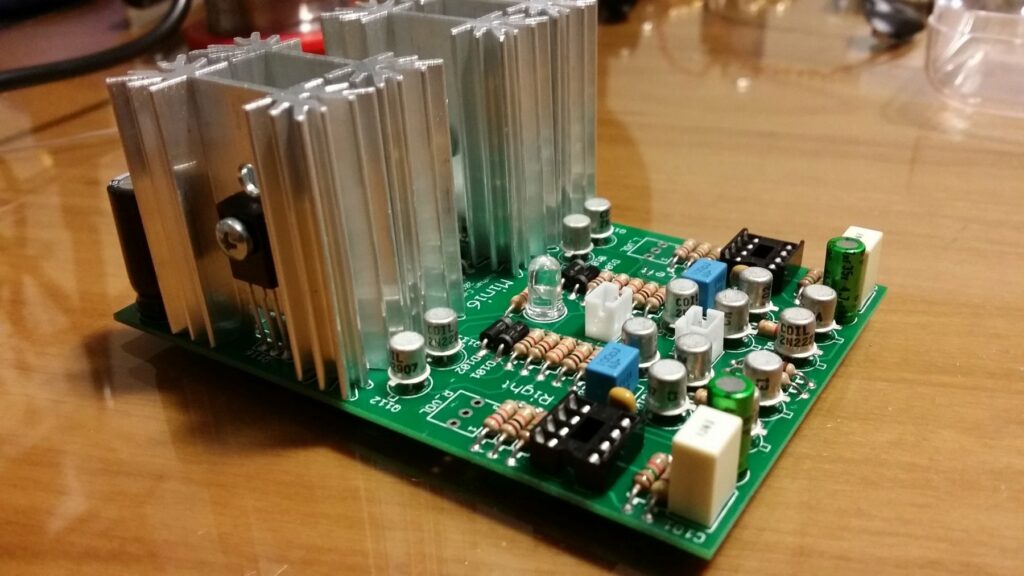
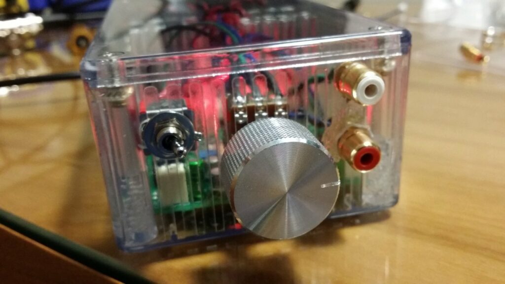
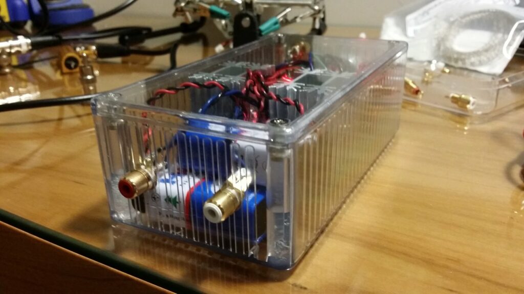
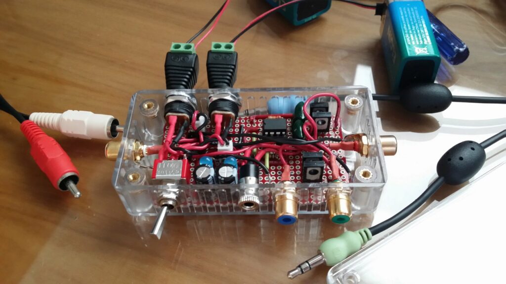
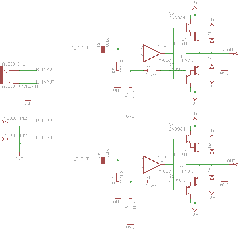
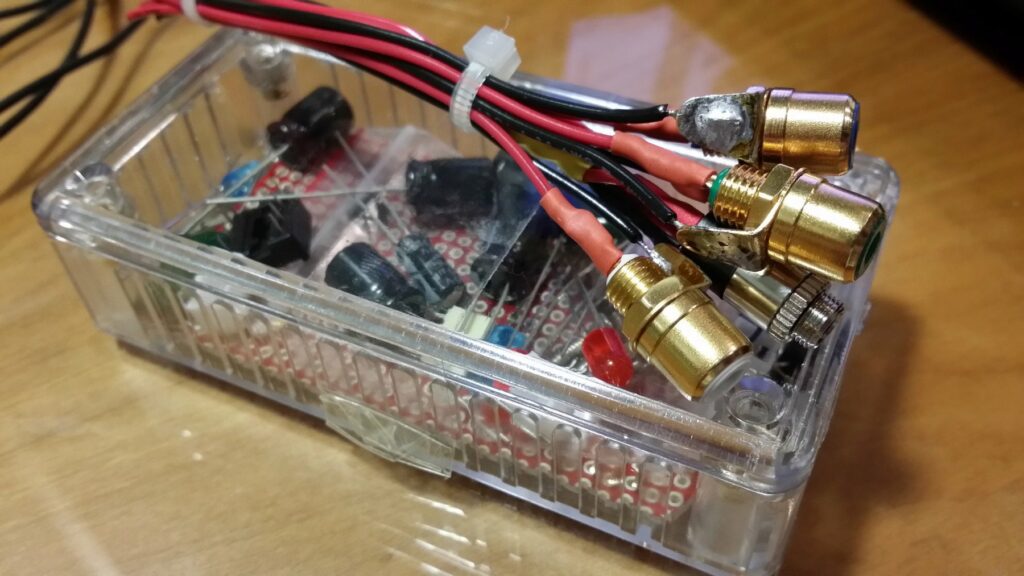
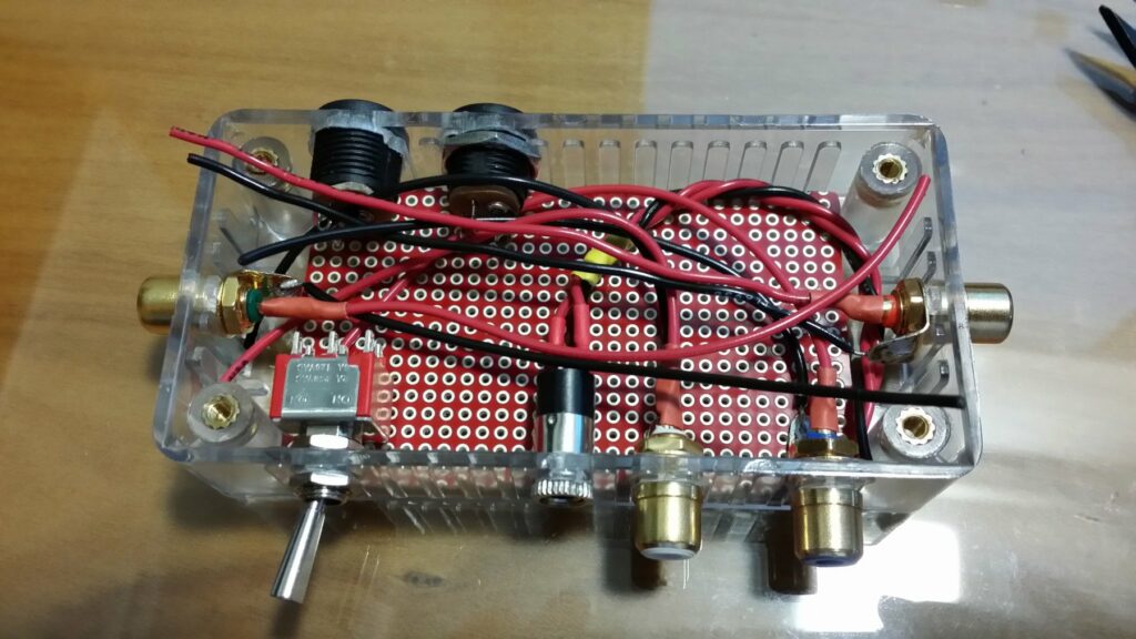
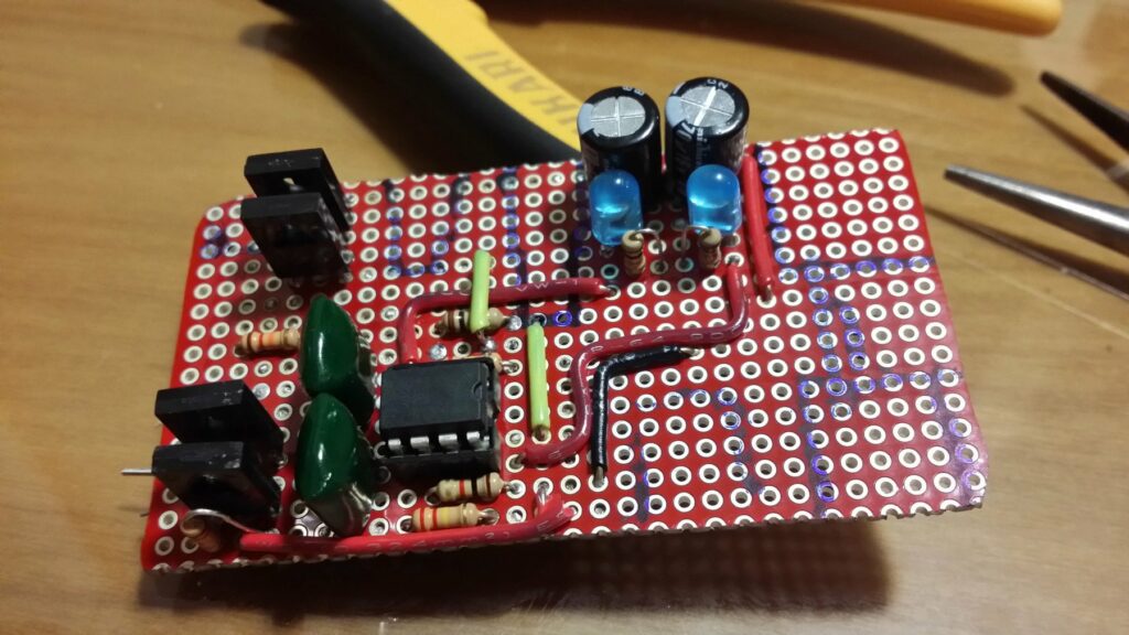
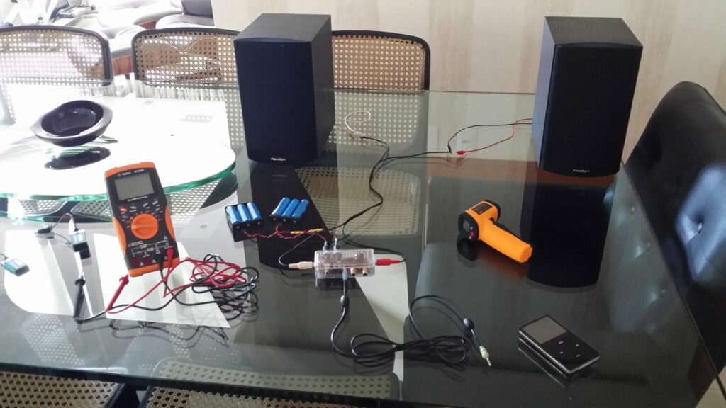
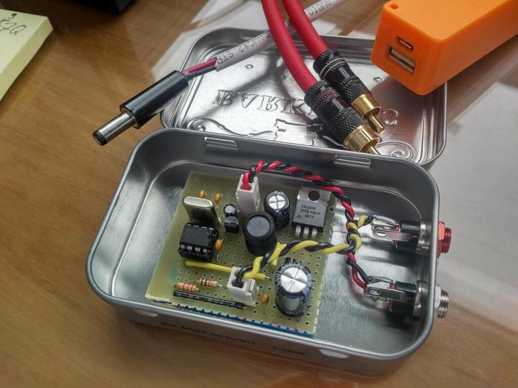
The idea for this project came because I built a nice portable Class-A headphone amplifier (blog post coming in the future) and I wanted a simple power supply for it when I was using it with my computer, so I had to step the 5V from the USB to the 9V required by the amplifier circuit, the amplifier even though it’s Class-A has a low current consumption, so the 2.5W from a normal USB was more than enough. Taking into consideration all this I needed a boost converter with the following specs:

  • 5V input at 450mA maximum to work with any USB port
  • 9V output able to source up to 110mA (more than enough for my amp)
  • Acceptable voltage ripple and noise since this will be used with pre-amps and the headphone amp
Circuit Schematic

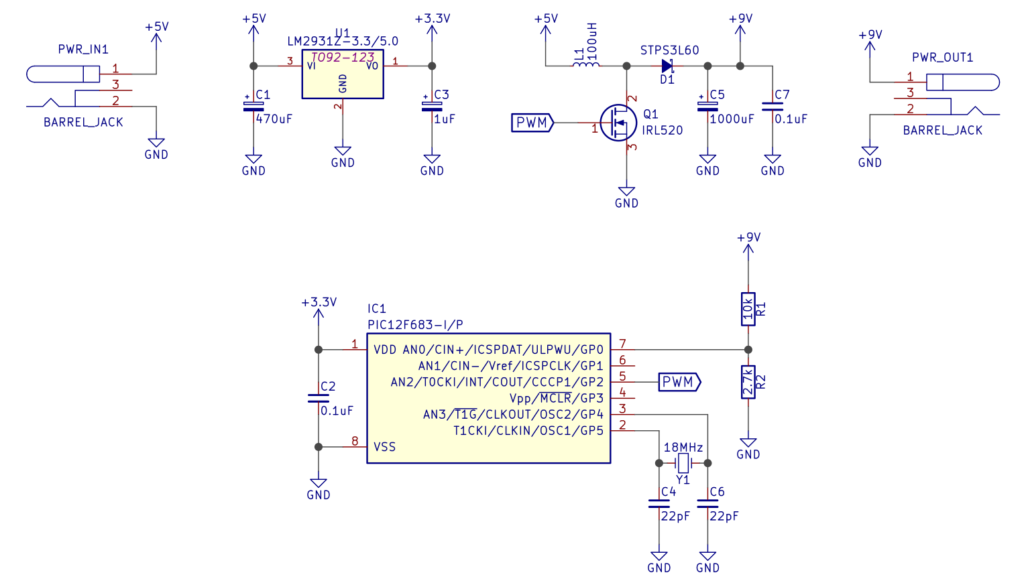
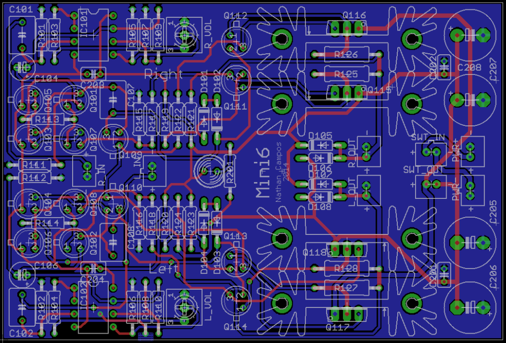
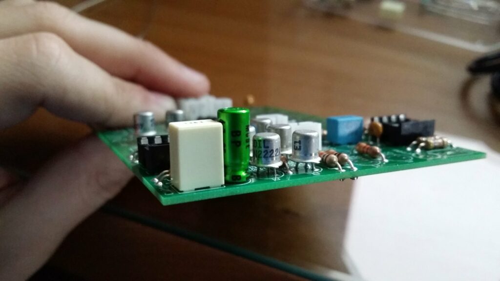
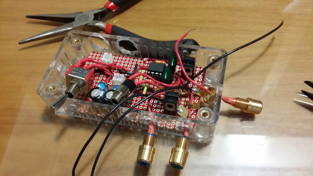
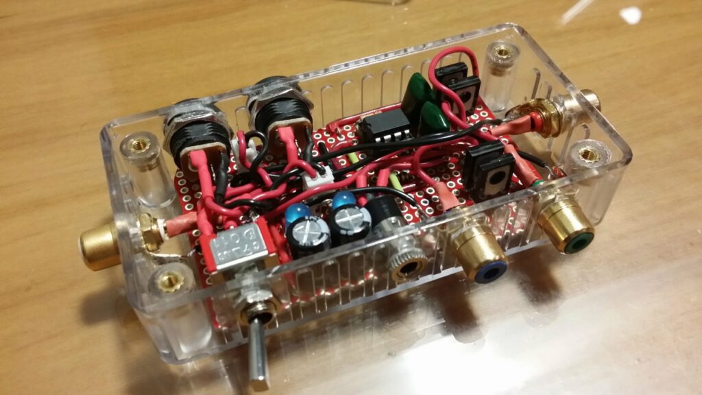
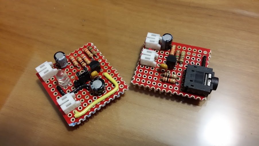
As you can see there’s not a lot happening, and that’s the beauty of this design, since it was made for low power projects it doesn’t require any of the complexities, it was designed to be minimalistic and easy to build for someone that is new to switch-mode converters. The entire feedback control loop is contained inside the PIC12F683 microcontroller, it is a pretty tiny and under-powered micro, but as you will see it works perfectly for this task.

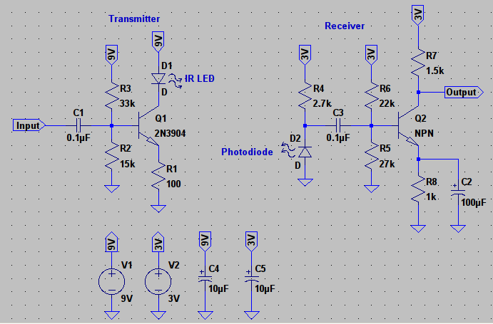
First the power input goes through a 3.3V regulator which provides power to the PIC and also acts as a voltage reference, then the microcontroller takes control of things and starts the PWM, pulsing current through the main inductor L1 while sensing the output voltage, if the voltage is lower than the set voltage it increases the PWM duty cycle, if the voltage is higher than the set voltage it decreases the PWM duty cycle, and that’s all you need to create a simple switch-mode converter. Here’s the code that runs the whole thing (I still need to improve it, so changes are coming):

If you’re a bit more experienced with DC-DC converters you’ll notice that the components used are a bit overkill, but that’s by design because I wanted very low ripple at the output, also in the topic of components, I selected a IRL520 MOSFET and this is very important, since I’m driving the gate with very low voltages a logic-level MOSFET is a must, if you want to use a regular MOSFET you’ll have to increase the gate voltage using a technique shown here.

A very handy tool for everyone designing their own DC-DC converters is Adafruit’s DIY DC-DC Boost Calculator, it was extremely useful to choose the components used in this project and it’ll surely help you in yours too. I’ve also written a R script to have a offline version of the calculator, it’ll be improved in the future, but it’s usable right now.

The only issue that I’m having with this project so far is the fact that no matter what I try, I can’t get the crystal to oscillate, I checked everything, set all the registers correctly and I still can’t get it to work, if anyone wants to help it’ll be greatly appreciated.

Noise figures

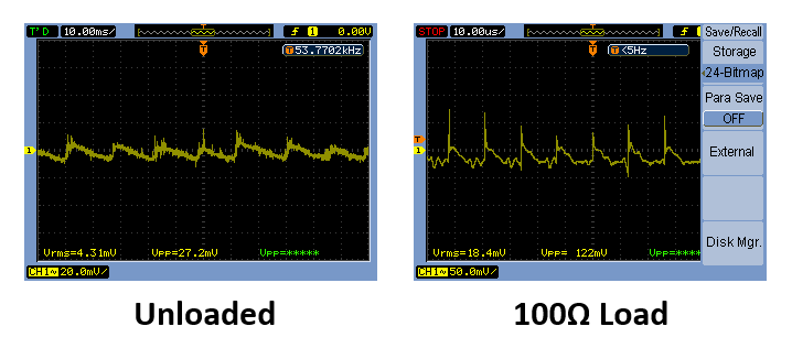
Since all my designs have a lot of local decoupling to keep any noise or ripple from the power source away from sensitive parts I didn’t care too much about having extremely low ripple/noise, but if you want to upgrade this you can add a small shunt regulator to really kill any ripple or just add a LC filter to the output.

If you’ve got any questions feel free to ask and I’m open to suggestions for improvement.


Mini6 Amplifier


This post was imported from my old blog Current Flow.

Finished project

I was a bit bored a couple of weeks ago so I decided to design a very simple discrete amplifier rated for 6W/channel just to make sure it wouldn’t oscillate and be more confident to build bigger ones.

Circuit Schematic

As you can see it’s a fairly simple design with a op-amp pre-amplifier and a discrete power amplifier. Building it was extremely simple, the difficult part is always mounting all the panel components and wiring everything.

Using build-bom to make my life easier while soldering

A while ago I built a program called build-bom to help me quickly find the component values when assembling a board. It’s a great use for a old EeePC that you may have laying around.

Components all soldered

One thing that you may have noticed is that I’ve used canned transistors instead of your typical plastic TO-92. The only reason I did this was because they looked cool and I have a bunch laying around.

If you want to know more about the amplifier check out the GitHub repo.


This post was imported from my old blog Current Flow.

Update: This project was my first try at building an amplifier, because of this it is pretty awful in terms of performance, it has very noticeable crossover distortion. For better designs please look at newer posts here.

Finalized circuit

Last week, I decided to take on a very simple project: build a very low distortion, reasonably powerful, battery-powered amplifier that could fit in a very small, transparent enclosure that I had.

The main idea was to have this very small amplifier that could be moved around the house and powered from some 18650 cells so that I could enjoy some music with my friends when they come for our regular LAN parties. Usually we use one of those crappy iPod dock/speaker things that everyone loves, but, personally, they don’t sound very good to me.

Since this was a quick project, I decided to make it as simple as possible to avoid any trouble. The easiest it could be was to use an audio op-amp driving a class B output made with Darlington transistors with some negative feedback to keep the distortion really low, so that’s what I did:

Circuit Schematic

I also designed a very simple peak detector to detect any clipping on the output to make sure the signal was as clean as possible, but, sadly, my case was so small that I couldn’t fit it in. Since it would be powered from 2 18650 packs (3 cells each) or a pair of 9V batteries, the power supply is extremely simplistic.

When all of the parts arrived, I decided to get everything prepared to be assembled the next day.

Parts ready to be assembled

Choosing where to put the jacks and switches was a bit tricky since the space inside the enclosure was extremely small.

Finished drilling all the holes for the connectors

Since I wasn’t patient enough to wait for a PCB, I decided to build the whole thing on a piece of protoboard which was a bit tricky because of the space the jacks took.

Circuit all soldered up

After soldering the headphone jack and on/off switch, mounted from the inside, it was time to solder the RCA jacks which had to be mounted from the outside. This was very difficult since I had to make the shortest cable possible while making sure that I could still lift the board up to solder the cable to the PCB.

Soldering the connectors to the board

Sliding the board back into place was extremely difficult, but after a lot of wiggling, it was perfectly placed on the bottom of the enclosure, and I was ready to plug the power jacks into the JST connectors on the board. It was the only way to mount them, otherwise I wouldn’t be able to lift the board to solder them.

Completed project

Since it was 1:38AM, I was quite tired, and since I had been working on this thing for 7 hours and 12 minutes, I decided that it was time to sleep and leave the enclosure closing and testing for the next day. (Obligatory picture of the pile of wires and component leads)

First thing to do in the morning was to test the little beast. This was the test setup (after using my oscilloscope and a dummy load to make sure everything was working fine). I had to use the living room table since my bench was a mess (as usual), and there was no space for the 2 speakers.

Testing the circuit in the living room

And that’s all! If you want more technical information about the project, be sure to visit the GitHub repo. If you want to discuss it, jump on over to the diyAudio thread.


This post was imported from my old blog Current Flow.

This week I’ve been experimenting with a very simple and cheap project for wireless transmissions, a lightwave AM transmitter and receiver based on Scott’s design, which was based on VK2ZAY’s design. In my final design I’ve increased the base biasing resistors to decrease the size of the coupling capacitor and also used a Darlington transistor to get more current gain.

Circuit Schematic in LTSpice

The transmitter is pretty straight forward, the input modulates the current passing by the LED, which modulates the intensity of light, if you’ve designed any class A amplifiers in the past you surely know how it works. The receiver is just a simple transimpedance amplifier, which is amplifying the signal quite a bit (~56x gain) since the transmitter will usually be a bit far from the receiver. You can do the same with a op-amp, but I much prefer a discrete circuit for these simple things.

You can put a buffer stage with a Darlington emitter follower on the output of the receiver so you can drive a speaker directly. Something that I would recommend is to add a small (10x gain maybe?) pre-amplifier for the transmitter, that way you’ll get a bit more signal if you’re source isn’t very loud, specially if you want to drive some high power LEDs, since you have a lot of current headroom with those.

If you want to experiment with different values in a simulation, here is the LTspice schematic. The best way to choose the best LED + photodiode combination to maximize the range is to build some breakout boards that you can plug different LEDs and photodiodes until you have the perfect combination.

Prototypes all soldered up

This post was imported from my old blog Current Flow.

Recently I’ve started using my Jornada 720 as a replacement for my iPad as a lab computer since it’s extremely tiny (space is very important in the bench) and can do practically everything I need my iPad for, of course I still have my main computer in the lab to program microcontrollers and do everything, but the Jornada is great to have near my working area so I can quickly check datasheets, schematics, and parts list while soldering or prototyping.

Very Old Lab Workbench

Usually when I’m prototyping or testing a board I have to check datasheets for pinouts, common voltages, etc. and Adobe Reader is great for this task:

Reading PDFs using Adobe Reader

In my main computer I keep a very well organized folder (and database, but I’m still researching the best way to get the DB into my j720 and keep them both synced) with datasheets for practically every electronic component I have in stock. So whenever I update the folder with more stuff I just rsync everything to my Jornada, and since it’s a nice Linux machine I’ve already wrote a nice script to automate things.

Component Datasheets
Folder Organization

Last, but certainly not least, I’ve built a small command line application a while ago called build-bom which gets a schematic file from my CAD program (EAGLE) and can output the parts list into HTML, CSV, or JSON. So whenever I’m populating a board I export the parts list to HTML and open it in my Jornada so I can know which part to place where in the board:

HTML export from build-bom