This post was imported from my old blog Current Flow.
I was a bit bored a couple of weeks ago so I decided to design a very simple discrete amplifier rated for 6W/channel just to make sure it wouldn’t oscillate and be more confident to build bigger ones.
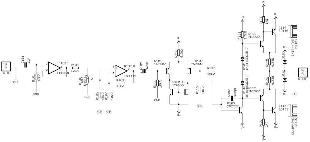
As you can see it’s a fairly simple design with a op-amp pre-amplifier and a discrete power amplifier. Building it was extremely simple, the difficult part is always mounting all the panel components and wiring everything.
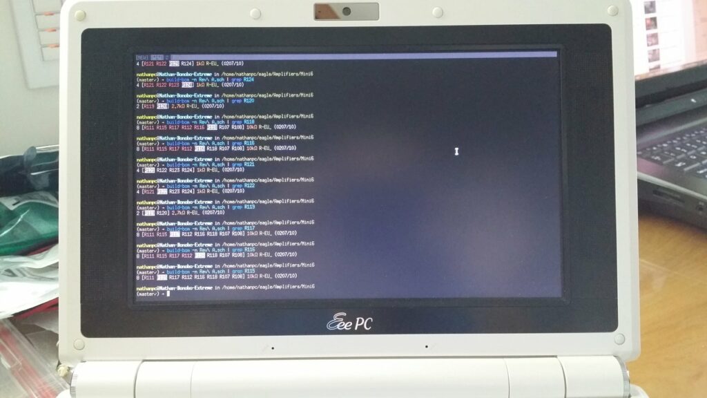
A while ago I built a program called build-bom to help me quickly find the component values when assembling a board. It’s a great use for a old EeePC that you may have laying around.
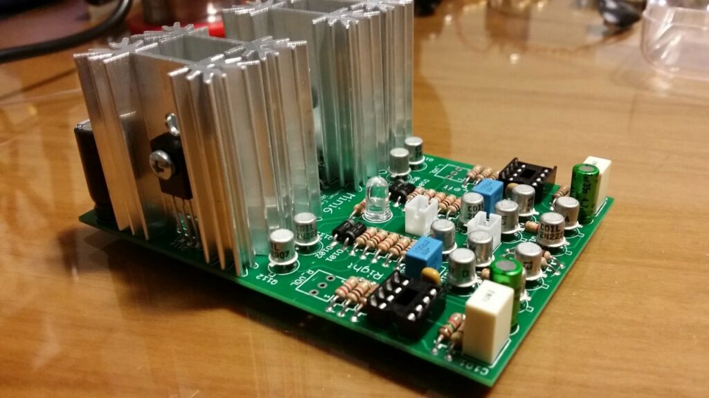
One thing that you may have noticed is that I’ve used canned transistors instead of your typical plastic TO-92. The only reason I did this was because they looked cool and I have a bunch laying around.
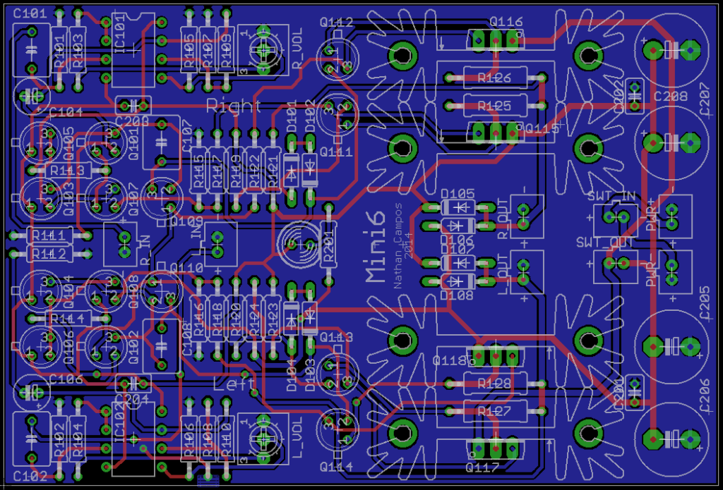
How the board looks like in CAD 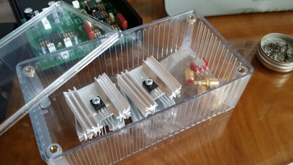
Organizing the components to begin soldering 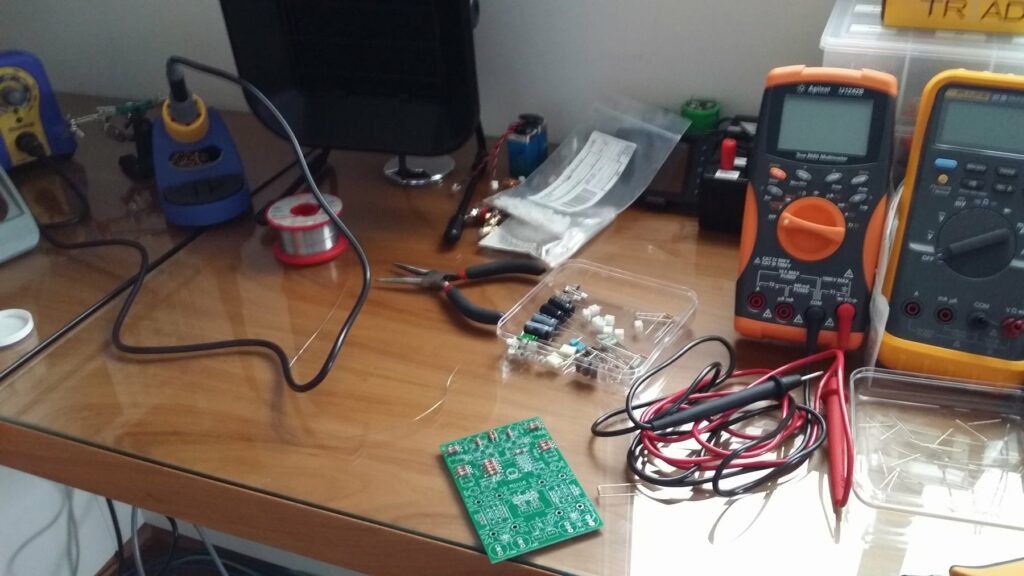
Started soldering 
Checking the values with my program 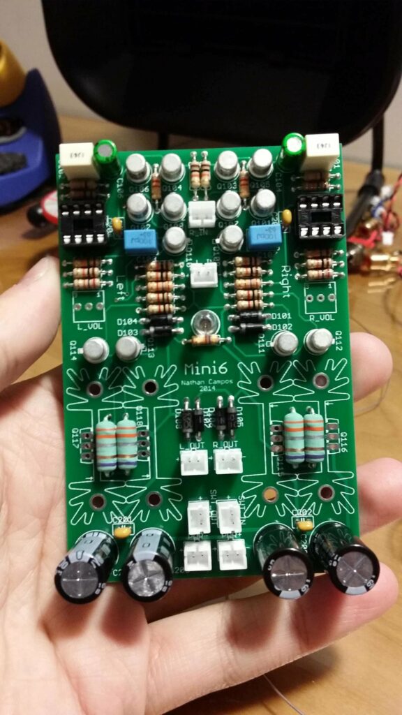
Top view of the board after soldering 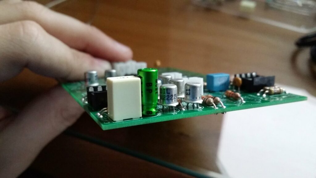
Side view of the board 
Board with the heatsinks 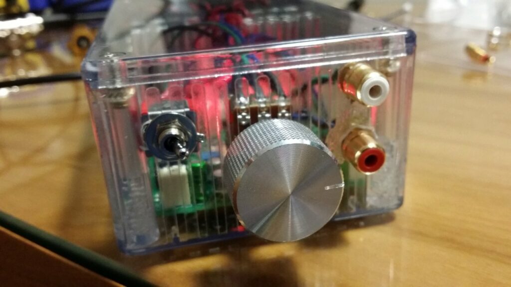
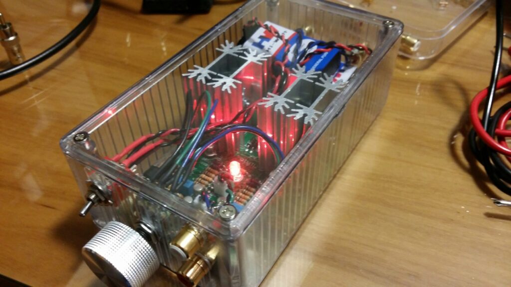
Front panel 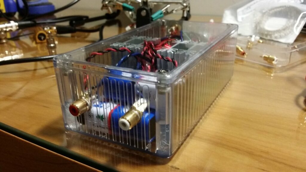
Back panel
If you want to know more about the amplifier check out the GitHub repo.